Pressure Design - Pipe & Pipe Fittings
Pressure Design of Pipe and Pipe Fittings according to EN 13480-3 (2017)
Pressure Design of Pipe and Pipe Fittings can be performed using the modules built into CAEPIPE which are independent of the piping flexibility analysis.
These modules can be launched through Layout frame > Misc > Internal Pressure Design: EN 13480-3 and Layout frame > Misc > External Pressure Design: EN 13480-3.
Note:
These modules perform Pressure Design of Pipe and Pipe Fittings ONLY using the equations given in the EN 13480-3 (2017) Code irrespective of the Analysis Code selected for piping flexibility analysis in CAEPIPE.
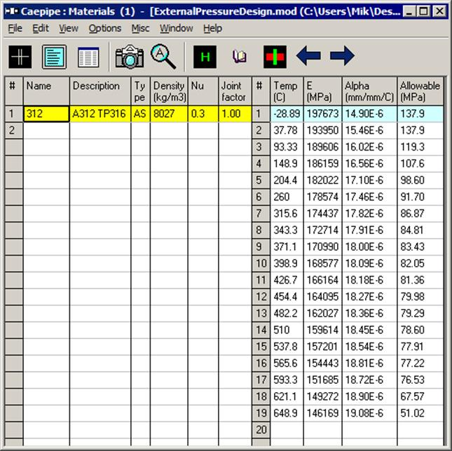
In case the pipe stress analysis is performed with an Analysis Code other than EN 13480-3 (2017), the Pressure Design modules will use the material allowable stresses corresponding to the maximum temperature T1 through T10 entered in the CAEPIPE stress model.
Internal Pressure Design of Pipe and Pipe Fittings
Snap shots shown below present a sample stress model developed to show the Internal Pressure Design calculations performed by CAEPIPE.
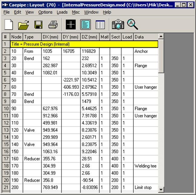
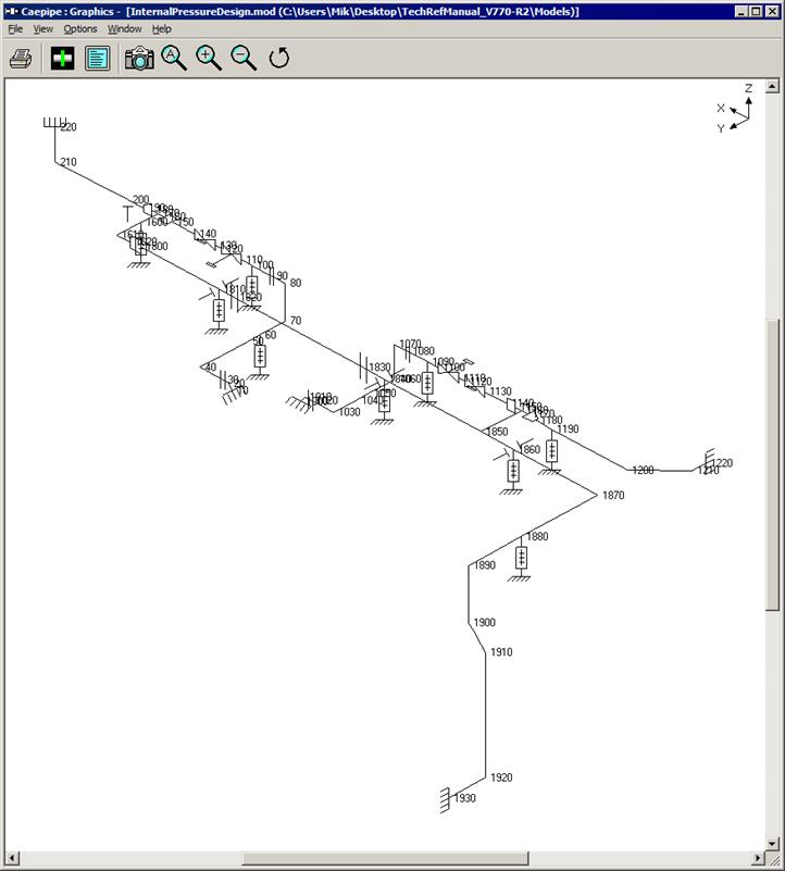
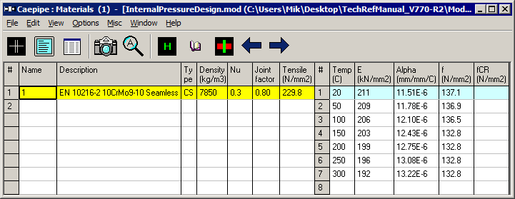
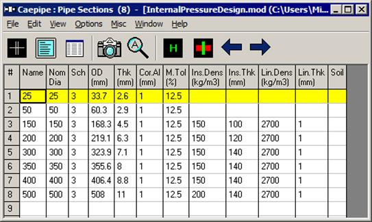
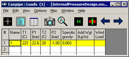
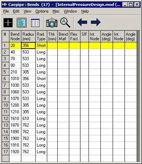
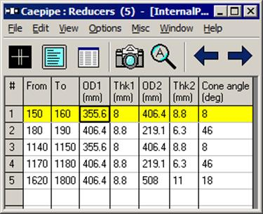
Internal pressure design calculations of pipe and pipe fittings according to EN 13480-3 (2017) are independent of element lengths entered. Hence, these calculations can be performed from the CAEPIPE model already developed for flexibility analysis. Equations used for performing Internal Pressure Design as per EN 13480-3 (2017) are provided in Section titled “Pressure Design of Pipe & Pipe Fittings” in the Code Compliance Manual.
Once the layout of the stress model as shown in the above snap shots is completed, the internal pressure design is performed through Layout window > Misc > Internal Pressure Design: EN 13480-3.
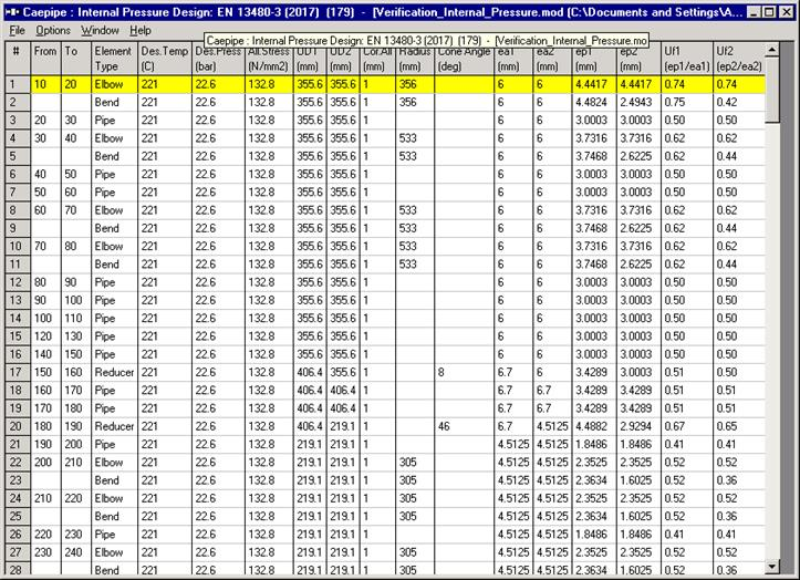
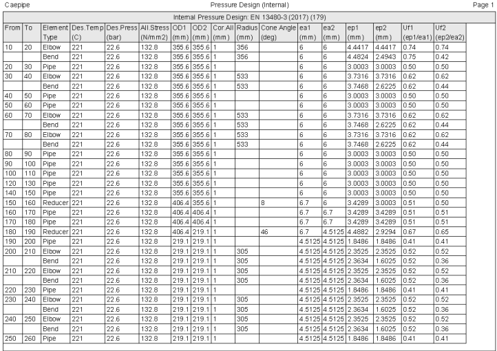
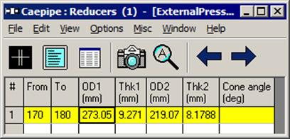
When executed, CAEPIPE automatically performs the pressure design calculations for Pipes, Elbows, Miters, Bends and Reducers for the entire stress model and displays the results as shown below.
It is observed that the ratios Uf1 and Uf2 are all less than 1.0, confirming that the Internal Pressure Design requirements of EN 13480-3 (2017) code are met for this stress model.
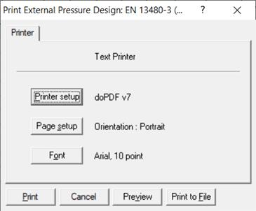
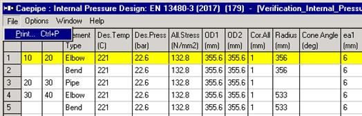
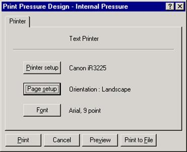
The results shown above can also be printed to the printer or to a file using the option File > Print.
External Pressure Design of Pipe and Pipe Fittings
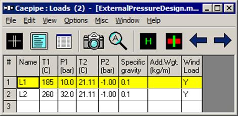
External Pressure Design module will function ONLY when the stress layout is defined with negative pressure (such as vacuum pressure).
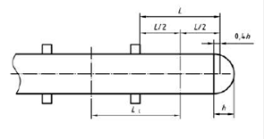
This module first calculates collapse pressure (same as buckling pressure), which is a function of span length “L” between the stiffeners placed on the piping (shown in figures below). Since the collapse (buckling) mode of deformation for a pipe element between two adjacent stiffeners is restrained by these stiffeners, shorter the span length L between the stiffeners, higher the collapse (buckling) pressure.
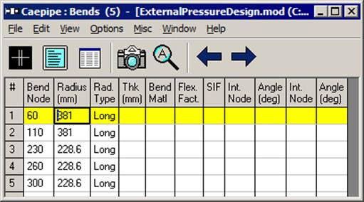
The External Pressure Design module assumes that a stiffener is located at each node of the CAEPIPE model. Hence, ensure that nodes are defined in CAEPIPE model only at locations where the stiffeners are attached to the piping. Even nodes where flanges or certain types of supports that restrain the collapse (buckling) mode of deformation should be included as “stiffener locations”. All other nodes at which the collapse (buckling) mode of deformation is not restrained (such as resting supports) should not be included in the CAEPIPE model for external pressure design calculations. In other words, the CAEPIPE stress model (that was developed for flexibility analysis) needs to be edited before performing the external pressure design.
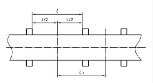
Single Pipe
Pipe with bend
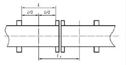
Pipe with flange connections
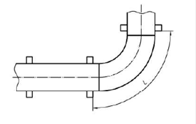
Pipe with bend or elbow with ‘L’ measured on extrados
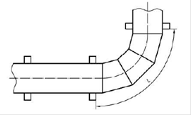
Pipe with miter with ‘L’ measured on extrados
The procedure given below will help in retaining ONLY those nodes of the CAEPIPE stress model (originally developed for flexibility analysis) prior to External Pressure Design calculations.
· Create a copy of the existing CAEPIPE stress model (developed for flexibility analysis).
· At whichever node the collapse (buckling) mode of deformation is NOT restrained, navigate to that element node in the layout window and use the option “Combine…” through Layout window > Edit. This action will remove that node by combining the two adjacent elements.
· Repeat the above step and remove all other nodes where the collapse (buckling) mode of deformation is NOT restrained, thereby retaining ONLY the stiffeners, flanges and supports that restrain the collapse (buckling) mode].
· Upon completion, save the model.
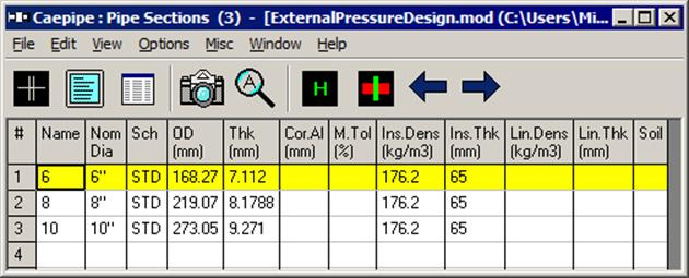
Snap shots shown below present a sample model developed to show the External Pressure Design calculations performed by CAEPIPE. As stated above, a copy of the original stress model was made and the model has been edited to include only those nodes on pipe where stiffeners, flanges and supports (that are equivalent to stiffeners from the point of view of restraining collapse mode of deformation) are attached.
Refer Section titled “External Pressure Design according to SS EN 13480-3” in CAEPIPE Code compliance manual for details on implementation.
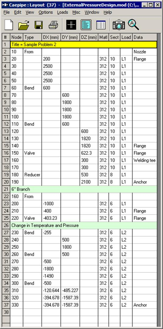
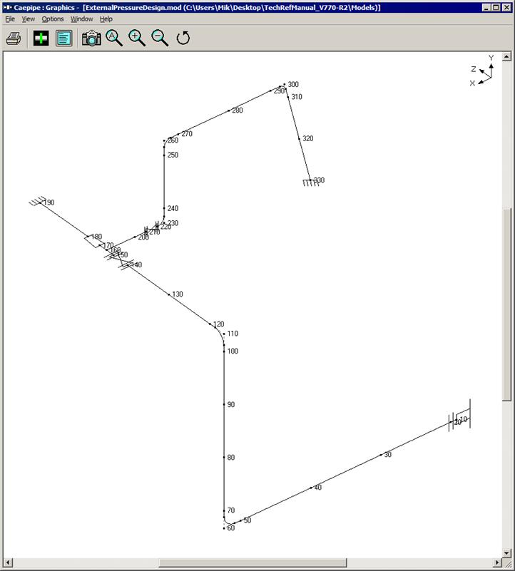
Once the layout of the stress model as shown in the above snap shots is completed, the external pressure design is performed through Layout window > Misc > External Pressure Design: EN 13480-3.
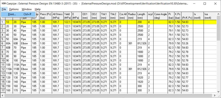
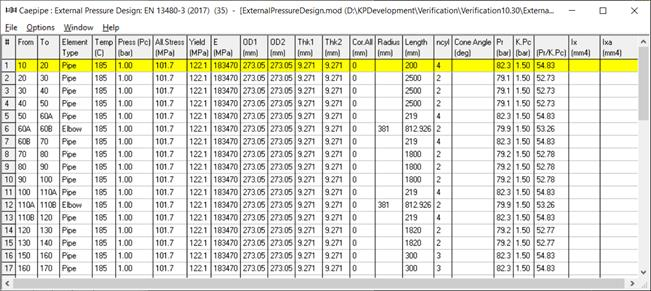
When executed, CAEPIPE automatically performs the external pressure design calculations for Pipes, Miters, Elbows, Bends and Reducers for the entire stress model and displays the results as shown below.
It is observed that the ratio [Pr/(KPc)] is much higher than 1.0 throughout the stress model, confirming that the collapse (buckling) pressures Pr calculated for all segments of the stress model are much higher than the corresponding peak negative pressures specified in the CAEPIPE model. In other words, the potential for any segment of this piping system to collapse (buckle) is very minimal.
The results shown above can also be printed to the printer or to a file using the option File > Print.