Rigid element
Use this element to model any “stiff” (relative to pipe) inline component.
The stiffnesses of 1 x 10¹²(lb/inch) in translational directions (axial and shear), and 1 x 10¹² (inch-lb./rad.) in rotational directions (bending and torsional) are used.
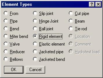
A rigid element is input by typing “ri” in the Type column or selecting “Rigid element” from the Element Types dialog.
The Rigid element dialog is shown.
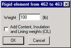
Weight
The required input is weight. It is applied as a distributed load along the length of the rigid element. To this empty weight, the Additional weight specified under Load column is added (to include weight of snow etc.).
Weight is to be input in lbf or kgf and NOT in mass units. Whenever mass is required for a calculation as in the case of forming Mass matrix for dynamic analysis, or in calculating inertia force as (mass x acceleration) for static seismic analysis, CAEPIPE internally computes the mass to be equal to (weight / g-value).
For Sustained load case analysis, weights of content, insulation and lining (as calculated using insulation thickness and its density as well as lining thickness and density) are added internally in CAEPIPE when the option “Add Content, Insulation and Lining weights (CIL)” is turned ON.
For the Empty Weight load case analysis, only weights of insulation and lining will be included, while the weight of content will be excluded when the option “Add Content, Insulation and Lining weights (CIL)” is turned ON.
Material density does not affect the weight of the rigid element.
Thermal expansion of the rigid element is calculated using the coefficient of thermal expansion from the Material column and temperatures from the Load column. Wind load is calculated using the section properties inclusive of insulation thickness.
These may be needed when you want to account for some hard-to-model element’s thermal growth, or to connect the center line of a large pipe to its outside surface, again to account for its (radial) thermal growth/contraction (which impacts the branch line), or to model a rigid, massless link between two points on the stress model.
To model any of these, input a rigid element, type zero for weight and ensure that the corresponding Load (specified on the Layout window under the Load column) used for this element does not have any Additional weight specified.