User Hanger
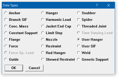
Use the “User Hanger” type for analyzing piping systems with existing variable spring hangers, which are different from spring hangers that need “to be designed” (for which you use the “Hanger” data type).A user hanger is input by typing “u” in the Data column and pressing Enter or selecting “User Hanger” from the Data Types dialog.
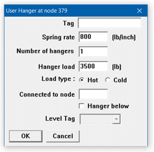
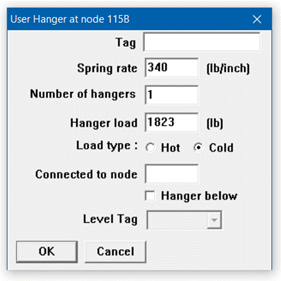
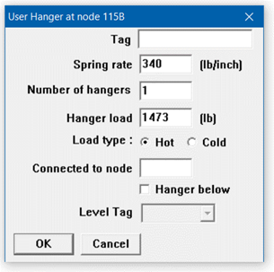
The User Hanger dialog is shown.
Spring Rate
The spring rate is required. For a constant support user hanger, input the spring rate as zero.
Number of Hangers
Type in the number of separate hangers connected in parallel at this node. The stiffness and load of each hanger are multiplied by the number of hangers to find the effective stiffness and load of the hanger support at this node.
Hanger Load and Load type
Input the hanger load, if known. Otherwise, leave it blank and CAEPIPE will calculate the load.
The hanger load may be specified as hot or cold using the Load type radio buttons.
When Cold Load and Spring Rate are input for User Hanger
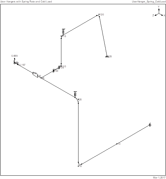
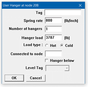
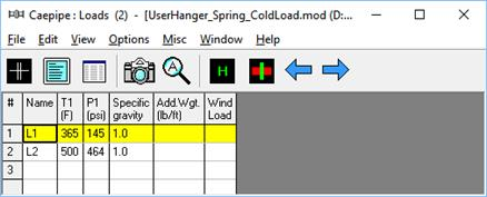
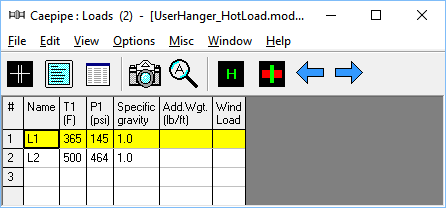
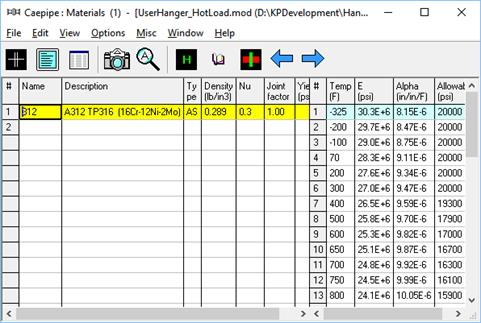
Snap shots shown below are from a CAEPIPE model with two (2) User Hangers defined at Nodes 20B and 115B. In this model, Spring rate and Cold load are input for each User Hanger as given below.
User Hanger at Node 20B User Hanger at Node 115B
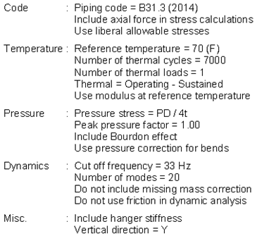
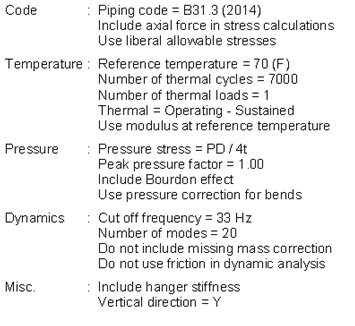
Analysis Options
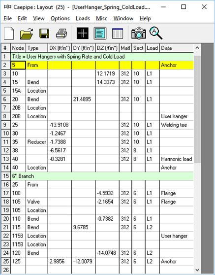
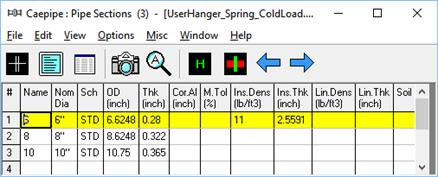
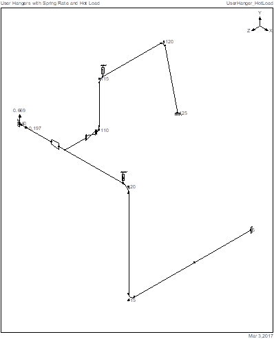
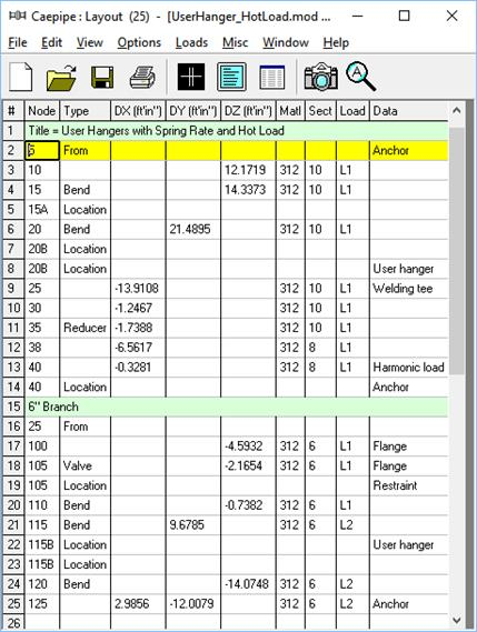
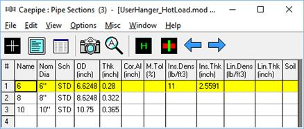
Details of Layout
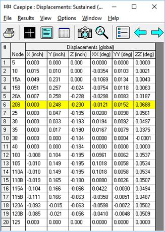
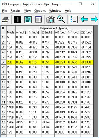
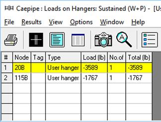
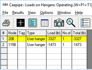
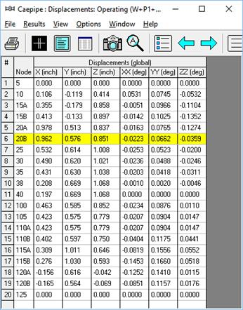
From the analysis results, Hanger Report as well as Displacements and Support Loads for Sustained & Operating load cases are presented below.
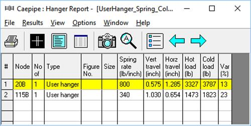
Given below are the Steps performed by CAEPIPE to arrive at the results shown above for User Hangers when “Cold load” and “Spring rate” are input.
Step 1: Compute Hot Load from Preliminary Sustained Load Analysis
Performs a preliminary sustained load analysis and computes hot loads for the two User Hangers by replacing them with Vertical Restraints.
To verify this step, remove the User Hangers at nodes 20B and 115B and instead add Vertical Rigid Restraints at those two nodes and perform a sustained load analysis. From the Analysis results, you will observe that the “Loads on Restraints” at nodes 20B and 115B for Sustained load case will be identical to the hot loads reported above in the Hanger Report for the model with User Hangers.
Step 2: Compute Vertical Travel from Preliminary Operating Load Analysis
Vertical Restraints added in Step 1 above at User Hanger locations are removed. The hot loads (calculated in Step 1) are applied as upward forces at the hanger locations. Vertical displacements at the hanger locations obtained from the operating load case analysis are the hanger travels.
To verify this step, remove the Vertical Restraints at Nodes 20B and 115B from the model developed in Step 1 above. Apply the hot loads as upward forces at Nodes 20B and 115B by choosing “Add to W+P” in CAEPIPE’s Force dialog and perform the analysis. Vertical displacement results at the User Hanger locations for the Operating load case will be identical to the Vertical Travel values reported above in the Hanger Report for the model with User Hangers.
Step 3: Perform Detailed Analysis
Performs once again the Sustained and Operating load case analyses by including the “Spring Rate” and “Cold load” input into CAEPIPE model at User Hanger locations.
To verify this step, to the model developed under Step 2 above add a skewed restraint in vertical direction at each User Hanger location with its stiffness equal to the “Spring Rate” for that User Hanger. In addition, add to the sustained load case (i.e., choose “Add to W+P” in CAEPIPE’s Force dialog) an upward force at each skewed restraint node that is equal to the Cold load for the corresponding User Hanger. The resulting Step 3 model is then analyzed. Displacements for the Sustained and Operating load cases obtained from this Step 3 model will be identical to the displacements obtained for Sustained and Operating load cases reported above for the model with User Hangers.
Now, from the Step 3 model results, we observe the following at the two skewed restraints.
Sustained load case
Support load at Node 20B [A] = Spring Rate x Sustained displacement at Node 20B
= 800 lb/in x 0.248”
=198.4 lb (comparing well with CAEPIPE result of 198 lb)
Support load at Node 115B [B] = 340 lb/in x 0.166”
= 56.44 lb (comparing well with CAEPIPE result of 56 lb)
Operating load case
Support load at Node 20B [C] = Spring Rate x Operating displacement at Node 20B
= 800 lb/in x 0.575”
= 460 lb (comparing well with CAEPIPE result of 460 lb)
Support load at Node 115B [D] = 340 lb/in x 1.030”
= 350.2 lb (comparing well with CAEPIPE result of 350 lb)
Using the above Support load and Cold load, CAEPIPE is computing and reporting the Loads on User Hangers as follows.
When the option “Include hanger stiffness” is turned ON
Sustained load case
Load on Hanger at 20B = -Cold load + Spring Rate x Sustained displacement at Node 20B
= -Cold Load + A
= -3787 + 198.4 = -3588.6 lb (matches with Hanger loads results)
Operating load case
Load on Hanger at 20B = -Cold load + Spring Rate x Operating displacement at Node 20B
= -Cold Load + C
= -3787 + 460 = -3327 lb (matches with Hanger loads results)
When the option “Include hanger stiffness” is turned OFF
Sustained load case
Load on Hanger @ 20B = -Hot load = -3327 lb
Operating load case
Load on Hanger @ 20B = -Hot load = -3327 lb
When Hot Load and Spring Rate are input for User Hanger
Snap shots shown below are from a CAEPIPE model with two (2) User Hangers defined at Nodes 20B and 115B. In this model, Spring rate and Hot load are input for each User Hanger as given below.
User Hanger at Node 20B User Hanger at Node 115B

Analysis Options
Details of Layout
From the analysis results, Hanger Report as well as Displacements and Support Loads for Sustained & Operating load cases are presented below.
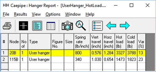

Given below are the Steps performed by CAEPIPE to arrive at the results shown above for User Hangers when “Hot load” and “Spring rate” are input.
Step 1: Compute Vertical Travel from Preliminary Operating Load Analysis
Performs a preliminary operating load analysis by including the hot loads input as upward forces at the hanger locations. Vertical displacements at the hanger locations obtained from the operating load case analysis are the hanger travels.
To verify this step, remove the User Hangers at Nodes 20B and 115B and instead apply the respective hot loads as upward forces at those two nodes by choosing “Add to W+P” in CAEPIPE’s Force dialog and perform the analysis. Vertical displacement results at the User Hanger locations for the Operating load case will be identical to the Vertical Travel values reported above in the Hanger Report for the model with User Hangers.
Step 2: Compute Cold Load
The Cold load is then computed using the Hot load entered and Vertical Travel obtained from Step 1 above as stated below.
Cold load = Hot load + Spring Rate x Vertical Travel
For example, at Node 20B,
Cold load = 3327 + 800 x 0.576 = 3787.8 lb.
Similarly, at Node 115B,
Cold load = 1473 + 340 x 1.030 = 1823.2 lb.
Step 3: Perform Detailed Analysis
Performs once again Sustained and Operating load case analyses by including the “Spring Rate” and “Cold load” (obtained in Step 2 above) into CAEPIPE model at User Hanger locations.
To verify this step, to the model developed under Step 1 above add a skewed restraint in vertical direction at each User Hanger location with its stiffness equal to the “Spring Rate” for that User Hanger. In addition, add to the sustained load case (i.e., choose “Add to W+P” in CAEPIPE’s Force dialog) an upward force at each skewed restraint node that is equal to the Cold load computed in Step 2 above for the corresponding User Hanger. The resulting Step 3 model is then analyzed. Displacements for the Sustained and Operating load cases obtained from this Step 3 model will be identical to the displacements obtained for Sustained and Operating load cases reported above for the model with User Hangers.
Now, from the Step 3 model results, we observe the following at the two skewed restraints.
Sustained load case
Support load at Node 20B [A] = Spring Rate x Sustained displacement at Node 20B
= 800 lb/in x 0.248”
=198.4 lb (comparing well with CAEPIPE result of 198 lb)
Support load at Node 115B [B] = 340 lb/in x 0.166”
= 56.44 lb (comparing well with CAEPIPE result of 56 lb)
Operating load case
Support load at Node 20B [C] = Spring Rate x Operating displacement at Node 20B
= 800 lb/in x 0.576”
= 460.8 lb (matching with CAEPIPE result of 461 lb)
Support load at Node 115B [D] = 340 lb/in x 1.030”
= 350.2 lb (matching with CAEPIPE result of 350 lb)
Using the above Support load values and Cold load, CAEPIPE is computing and reporting the Loads on User Hangers as follows.
When the option “Include hanger stiffness” is turned ON
Sustained load case
Load on Hanger at 20B = -Cold load + Spring Rate x Sustained displacement at Node 20B
= -Cold Load + A
= -3787.8 + 198.4 = -3589.4 lb (matches with Hanger loads results)
Operating load case
Load on Hanger at 20B = -Cold load + Spring Rate x Operating displacement at Node 20B
= -Cold Load + C
= -3787.8 + 460.8 = -3327 lb (matches with Hanger loads results)
When the option “Include hanger stiffness” is turned OFF
Sustained load case
Load on Hanger at 20B = -Hot load = -3327 lb
Operating load case
Load on Hanger at 20B = -Hot load = -3327 lb
Connected to Node
By default the hanger is connected to a fixed ground point which is not a part of the piping system. A hanger can be connected to another node in the piping system by entering the node number in the “Connected to” node field. This node must be directly above or below the hanger node.