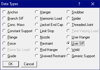
User SIF
User SIF (Stress Intensification Factor) may be used to specify SIF at a node where there is normally no SIF internally calculated (i.e., at a non-bend or non-tee node) or to override any internally calculated SIF at the node.
Use this for any component that needs an SIF value such as non-right angle tees, nonstandard tees or branch connections, flanges, etc., for which the chosen piping code does not specify a SIF, or you want to override the code’s SIF. For example, in case of a bend or a tee, CAEPIPE calculates the SIF according to the selected piping code. To override the calculated SIF, specify a User SIF. Note that a User SIF is applied to all elements that come together at this node.
A User SIF is input by typing “user s” in the Data column or selecting “User SIF” from the Data types dialog.
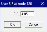
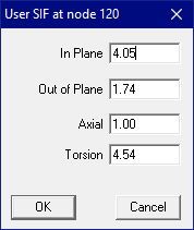
Depending on the piping code selected, either a single value User SIF (ASME Class 2 and Class 3) or In-plane, Out-of-plane, Axial or Torsion values of User SIF (B31.x code with B31J turned ON) or other User SIFs may be input. Sample dialogues for different codes are shown below.
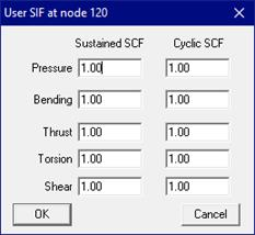
ASME Class 2 & Class 3 codes, RCC-M, DNV, etc.,
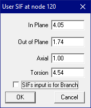
ASME B1.x codes with B31J ASME NM.2 IGEM
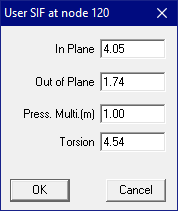
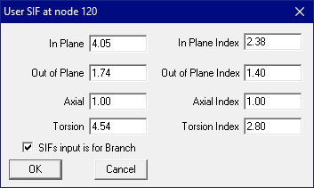
B31.3 code (2024 & later)
As per para. 320.1(b) of ASME B31.3 (2024), Ii = ii, Io = io and It = it from Table 1-1 of ASME B31J (2023) for components of sketches 1.1 through 1.3 and sketches 3.1 through 5.1 shown in ASME B31J (2023).
For components of sketches 2.1 through 2.6 of ASME B31J (2023), Ii, Io and It are taken as the smaller of (1) and either (2) or (3) below.
(1) 0.75 times the applicable stress intensification factor from Table 1-1 of ASME B31J (2023)
(2) t/T times square root of applicable stress intensification factor from Table 1-1 of ASME B31J (2023) when t/T > 1.0
(3) Square root of applicable stress intensification factor from Table 1-1 of ASME B31J (2023) when t/T <= 1.0
When the Do/T ratio for any component is greater than 50, then Ii, Io and It should be divided by (1.3 − 0.006Do/T), where, t = branch thickness, Do = Run OD, T = Run Thickness.
In CAEPIPE Version 13.20, the option “SIFs input is for Branch” has been introduced to allow users to input both SIFs and Indices for the User SIF defined at a Branch Node [corresponding to the sketches 2.1 through 2.6 of ASME B31J (2023)]. When this option is turned ON, then CAEPIPE displays a dialog box, as shown in the figure above.
Conversely, if a User SIF is defined at a node with the “SIFs input is for Branch” option turned OFF, then CAEPIPE will apply the following for ASME B31.3 (2024) in Stress calculations for Sustained and Occasional load cases.
In Plane Index (Ii) = In Plane SIF (ii)
Out Plane Index (Io) = Out Plane SIF (io)
Axial Index (Ia) = Axial SIF (ia)
Torsion Index (It) = Torsion SIF (it)