Code Compliance
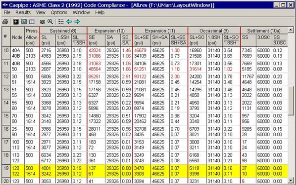
Here, CAEPIPE displays the stresses on an element-by-element basis. Sorted stresses screen (i.e., the previous results item) shows stresses at nodes sorted in the descending order of stress ratios. In this Code Compliance results item, CAEPIPE displays stresses for each element (highlight is on element 19, nodes 120 and 122).
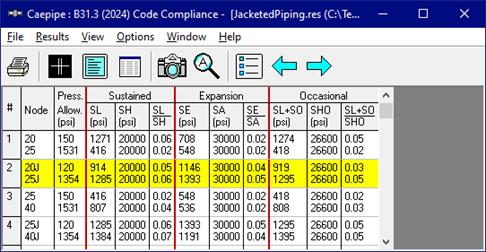
From the sample “Code Compliance” results of CAEPIPE shown below, you will observe that the 2nd Column titled “Press. Allow” output the following for each element.
1. First row outputs the “Peak Pressure” input for that element.
2. Second row outputs the “Calculated Allowable Pressure” for that element as per the equation provided in the corresponding piping code selected for analysis. Please note, when the “Peak Pressure” input for an element exceeds the “Allowable Pressure” computed for that element, then CAEPIPE will change the display color of Peak Pressure to RED.
For a Jacketed Pipe or Jacketed Bend, the allowable pressure for the core pipe is computed assuming the core pipe (i.e., inner pipe) to be stand-alone [without accounting for any internal pressure of the jacket pipe (i.e., outer pipe)]. For the jacket pipe, the allowable pressure is similarly computed assuming the jacket pipe to be stand-alone.
The computed allowable pressure is then compared with the specified Peak Pressure. For example, in the case of the Jacketed Pipe between Node 20J and Node 25J (as highlighted below), the Peak Pressure is specified as 120 psi. The computed allowable pressure of 1354 psi is then compared against this 120 psi Peak Pressure.
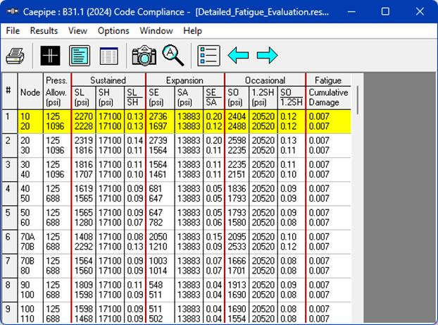
When the Detailed Fatigue Evaluation is enabled in the analysis for applicable piping codes, CAEPIPE will display additional column under the "Fatigue" section. This column will show the cumulative damage factor calculated from all the selected expansion load cases at each element, as illustrated below.