Support Loads
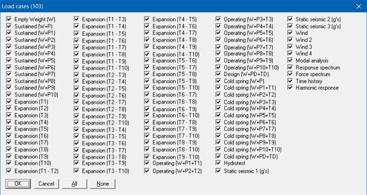
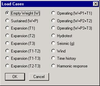
Support Loads are shown for all support types. For a support type, the support loads can be shown for all load cases by clicking on the black right/left arrow or simply press arrow keys on the keyboard. A list of load cases can be shown by clicking on the Load cases button.

When Random Vibration Load cases are included for NONE code, then CAEPIPE will show the load cases screen as shown below.
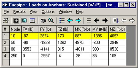
Support loads on all the supports in the model are shown in the next window. The window first shows anchor loads, if present. Then, when you click on the left or right white arrow, it shows you load at different supports.
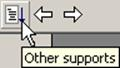
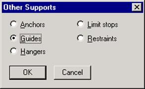
You can find out which other supports are in the model by clicking on the Other Supports button (immediately to the left of the left white arrow button). When you click on this button, the list of available support types is shown. Select the type.
In any window of CAEPIPE, whenever it displays the results in LCS, it will label the heading texts with the “Lower Case” letters. For example, the “Forces & Moments” in LCS are designated using “fx/fy/fz” and “mx/my/mz”. Similarly, the displacements in LCS using “x/y/z/xx/yy/zz”.
On the other hand, CAEPIPE displays the results in GCS by designating the heading texts with the “Upper Case” letters”. For example, the “Forces & Moments” in GCS are designated using “FX/FY/FZ” and “MX/MY/MZ” and the displacements in GCS as “X/Y/Z/XX/YY/ZZ”.
In summary, CAEPIPE displays / output the “Support Loads” for different types of supports in different coordinate systems as stated below.
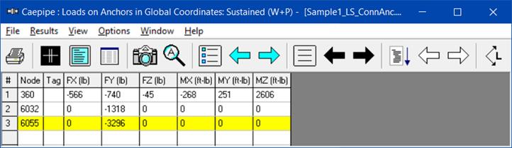
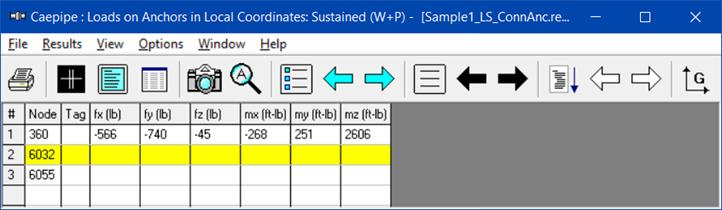
a. Anchor – By default in Global Coordinate System (GCS). Starting Version 13.00, user can view the “Anchor Load” in LCS by clicking the icon “L” available in the tool bar. When an Anchor is defined in a 3D space without a connecting element, then CAEPIPE will leave the forces and moments fields for that Anchor as BLANK when the option LCS is turned ON. See the snapshot shown below for Node 6032 and Node 6055 where Anchors are defined in 3D space without a connecting element.
b. Rigid Restraints – Always in GCS.
c. Guide – By default in Local Coordinate System (LCS). User can view the “Support Loads” in GCS by clicking the icon “G” available in the tool bar.
d. Limit Stops (Resting / Roller Supports) – By default in LCS. User can view the “Support Loads” in GCS by clicking the icon “G” available in the tool bar.
e. Skewed Restraints – Always in the direction of the support defined.
f. Spring Hangers / Rod Hangers / User Hanger / Constant Support Hangers – Always in Global Vertical direction.
In addition to the above, an Excel utility that converts Global Forces & Moments to the Local Forces & Moments once the required values are input is available at www.sstusa.com/downloads/GCS_LCS.xlsx.
To validate this Excel sheet procedure, two (2) CAEPIPE models were analyzed. First one has an Anchor attached to a skewed pipe wherein the Anchor loads are output in GCS (www.sstusa.com/downloads/BMS.mod). In the 2nd model, the Anchor has been replaced with 6 skewed restraints (3 translational and 3 rotational) in the adjacent element’s LCS system. The GCS results from the first model were entered in the Excel sheet in order to obtain forces and moments in LCS. These forces and moments in LCS are identical to the results from the 2nd model with skewed restraints (www.sstusa.com/downloads/BMS_SR.mod). We recommend that an independent validation of the excel procedure is carried out at your end to convert Global Forces & Moments to the Local Forces & Moments.
Note:
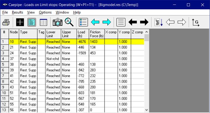
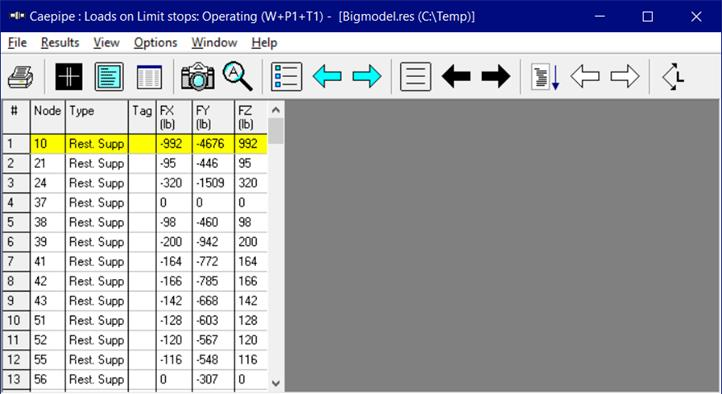
When you transform the Limit Stop loads from Local Coordinate System (LCS) to Global Coordinate System (GCS), then CAEPIPE will transform the Friction Force acting on the Limit Stop surface (computed by CAEPIPE in LCS) into two orthogonal LCS directions as 0.707 * Friction Force and then transforming the resulting LCS Friction Forces into GCS.
For example, for the Resting Support at Node 10 shown above (i.e., a Vertical Limit Stop in Global +Y direction), CAEPIPE will transform the resultant Friction Force of 1403 lbs acting on the Limit Stop surface into two orthogonal LCS values as 992 lbs (= 0.707 * 1403) and then transform them into Global FX and FZ directions for support design as shown above.
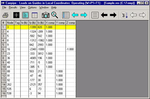
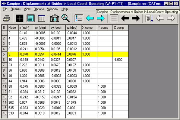
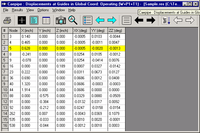
When a Guide is located in a vertical section of pipe, then the local x-axis for the Guide is vertical, whereas the local y-axis and local z-axis are in the horizontal plane. Local Coordinate System (LCS) for the Guide can be displayed through View > List > Guide and right-click mouse and select the option “Show LCS”. Since the pipe can freely move axially at the Guide (assuming zero friction), only lateral forces fy and fz are generated at the Guide in the local y-axis and local z-axis directions. On the other hand, pipe displacements at the Guide can be seen both in Global and Local Coordinate Systems. These can be seen in the snapshots below.
Results from Multiple Thermal, Seismic and Wind Loads
Displacements, Support Loads, Element Forces, etc., are calculated for the below shown thermal, Seismic and wind load cases, among others. The sorted stresses screen will always display for a specific node the highest expansion stress among all the selected thermal load cases. Similarly, if any of the four wind load cases happens to be the worst among all occasional loads for a specific node, then that occasional stress value will be shown under occasional stresses.