Tutorial for Fatigue Evaluation of Piping Systems
The following are the Steps for performing “Fatigue Evaluation” using CAEPIPE.
General
Fatigue analysis is an essential aspect of evaluating the long-term reliability of piping systems, especially those exposed to cyclic loading. Over time, repeated stress fluctuation - whether due to changes in temperature, pressure, or mechanical/flow-induced vibrations - can lead to the initiation of microscopic cracks to start with, followed by propagation of those cracks and eventual failure. The study of fatigue is essential for ensuring the reliability and longevity of piping components in various applications, such as process, power, nuclear, aerospace, petrochemical, chemical etc.
Starting Version 13.00, CAEPIPE (included in CAEPIPE 3D+) simplifies the fatigue analysis process by automatically checking against design codes and providing fatigue life estimates based on the cyclic loads experienced by the piping system. ASME Section VIII Division 2 provides guidelines for applying fatigue evaluation rules to piping and other pressure-retaining equipment. Where applicable, these guidelines have been followed in the methodology implemented in CAEPIPE. CAEPIPE has the ability to perform both detailed and simplified fatigue evaluation. Below are the details related to Fatigue Evaluation by CAEPIPE.
Detailed Fatigue Evaluation
Detailed Fatigue Evaluation is performed as per Miner’s Rule which is based on Cumulative Damage Theory. This theory states that fatigue damage accumulates over time and failure occurs when the accumulated damage reaches a critical value, typically set to 1. The rule is mathematically expressed as:

where, D = Total cumulative damage,  = Actual number of cycles at alternating stress level i,
  = Number of cycles to Failure at stress level i (from the S-N curve).
“When the total damage D equals or exceeds 1.0, then the fatigue evaluation is considered to have failed.”
The number of cycles to failure  is found using the S-N curves (Wöhler Curves), which are either input by the user (or) imported from ASME Section VIII, Division 2 (2021). The stress amplitudes (or alternating stress) are computed as one-half of total stress range (SE/2) at each node. This alternating stress is then used to find the corresponding number of cycles to failure (Ni) from the S-N curves.
The current version of CAEPIPE is supplied with 7 Fatigue Curves corresponding to the Figures 3-F.1 through 3-F.7 of ASME Section VIII, Division 2 (2021). Users can also add their own Fatigue curves and import them into CAEPIPE. Please refer to CAEPIPE User’s Manual for further information.
Note:
Starting Version 13.10, CAEPIPE performs detailed fatigue analysis node-by-node to check the cumulative damage due to various expansion load cases at each node. When the Cumulative Damage is less than 1.0, the stress layout is considered to be safe. On the other hand, when the Cumulative Damage exceeds 1.0, the user needs to make appropriate changes to the piping layout including support scheme in order to meet the above Fatigue requirement.
Simplified Fatigue Evaluation
Given below is the equation used in computing the total number of “equivalent reference displacement stress range cycles (N)” for Simplified Fatigue Evaluation.
where
NE = number of cycles of the reference displacement stress range, SE
Ni = number of cycles associated with the displacement stress range, Si
qi = Si/SE
SE = reference displacement stress range, psi (kPa) = Maximum stress range computed among the displacement stress ranges selected by the user for Simplified Fatigue Evaluation.
Si = maximum computed stress range for the ith displacement stress range.
x=1 or 3 or 5 based on the analysis Code selected. Please refer to CAEPIPE Code Compliance Manual for further details.
Once the “equivalent reference displacement stress range cycles (N)” is computed, then CAEPIPE uses this “N” to compute the Stress Range Reduction Factor (f or U) as per the piping code selected for analysis.
Actual Number of Cycles to be Input for Detailed and Simplified Fatigue Analysis:
In CAEPIPE, the actual number of cycles associated with each selected expansion load case can be entered as shown below. When Simplified or Detailed Fatigue Analysis is enabled, CAEPIPE utilizes this table (containing the actual number of cycles for the selected load cases) to perform both Simplified and Detailed Fatigue Analysis. Please note, when any of the load cases is not to be included in the Fatigue Evaluation, then leave the ‘Number of Cycles (N)’ field for that load case BLANK as shown below.
When the Detailed Fatigue Analysis is turned ON, CAEPIPE uses the “Fatigue Cycles” input by the user through Layout Window > Misc > Fatigue Cycles to compute the “Cumulative Damage (D)” as outlined above under ‘Detailed Fatigue Evaluation’.
Similarly, when Simplified Fatigue Analysis is turned ON, CAEPIPE uses the “Fatigue Cycles” input by the user through Layout Window > Misc > Fatigue Cycles for calculating the “equivalent reference displacement stress range cycles (N)”, which then is used to compute the stress range reduction factor (‘f’ or ‘U’) as detailed above under the section titled ‘Simplified Fatigue Evaluation’.
For better clarity, refer to the example given below for inputting the Fatigue Cycles table:
Consider a piping system that operates at three different temperature levels, each with a corresponding number of cycles over its service life and with the reference temperature of  .
.
10000 cycles of 
18000 cycles of 
5000 cycles of
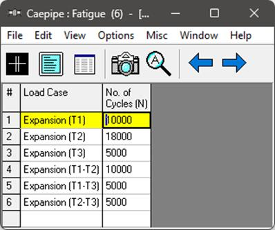
With reference to the above temperature ranges, the number of cycles that can be entered in CAEPIPE for each load case are as follows.
For Expansion  , the number of cycles=10000
For Expansion  , the number of cycles=18000
For Expansion  , the number of cycles=5000
For Expansion  , the number of cycles = Min(
  = Min (10000,18000) = 10000
For Expansion  , the number of cycles = Min(
  = Min (10000,5000) =5000
For Expansion  , the number of cycles = Min(
  = Min (18000,5000) = 5000
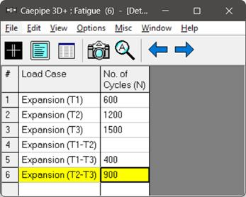
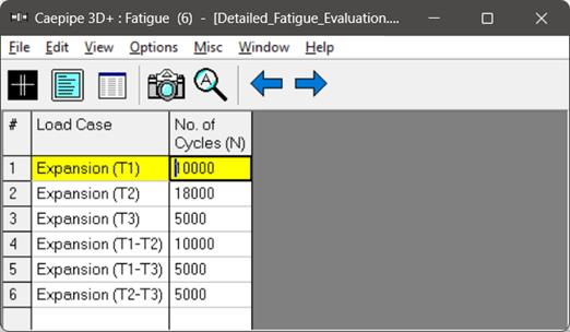
Accordingly, the Fatigue Cycles table in CAEPIPE is to be input as shown below.
The above approach to input the number of cycles is conservative as the sum of the Number of Cycles input is greater than the sum of actual number of cycles (i.e., [53000 = 10000+18000+5000+10000+5000+5000] > [33000 = 10000+18000+5000]). There may be alternate ways to input the number of cycles, such as “combining” or "lumping" the ranges of variations to produce the maximum effect as stated in Clause NB-3553 ‘Fatigue Usage’ of ASME Section III, Subsection NB (2021).
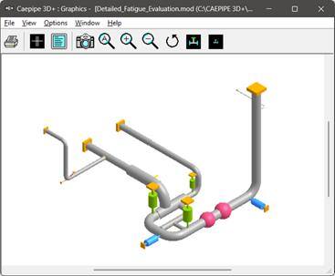
Step 1:
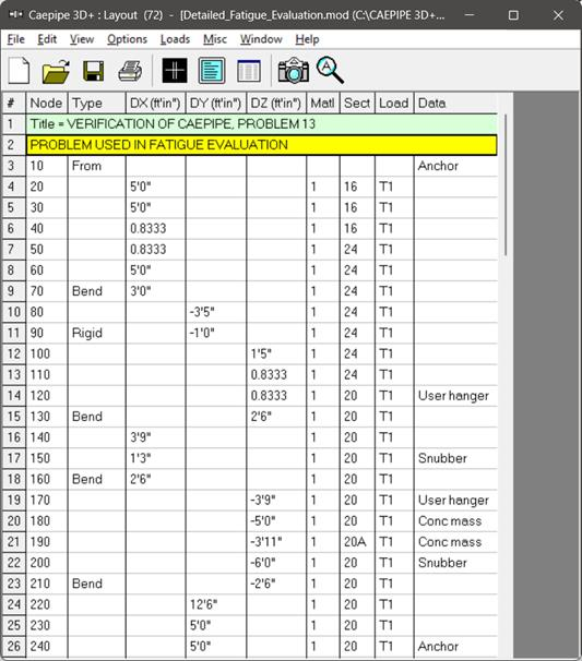
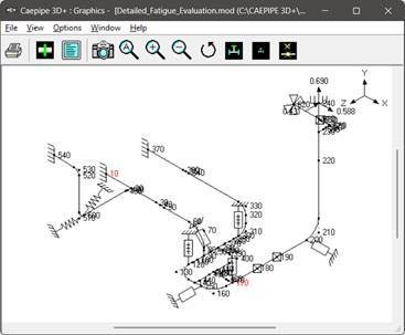
Snapshots shown below are from a sample CAEPIPE Stress layout that is used for Detailed and Simplified Fatigue Evaluation (see the “Detailed_Fatigue_Evaluation.mod” file). The piping code selected for this analysis is ASME B31.1 (2024).
Step 2:
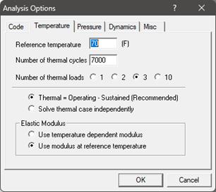
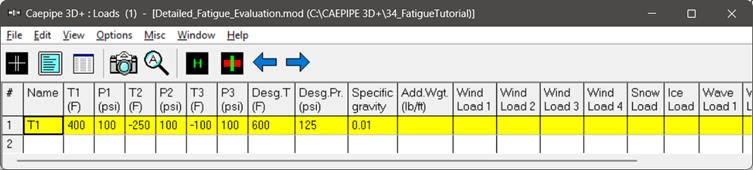
As explained above, this stress layout is assumed to be operating at three different temperature levels T1, T2 and T3 as 400 deg.F, -250 deg.F and -100 deg.F respectively with the reference temperature as 70 deg. F and Pressures P1, P2 and P3 as 100 psi. These loads can be input into CAEPIPE as follows.
Select the “Number of thermal loads” as 3 through Layout Window > Options > Analysis > Temperature.
Input the Temperatures and Pressures for Operating and Design load cases as given below through Layout Window > Misc > Loads.
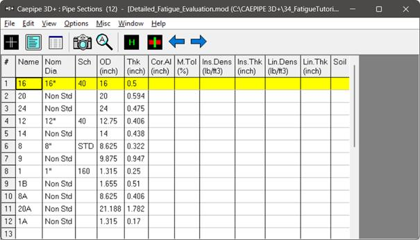
Step 3:
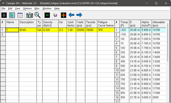
Section properties and Material used for this stress layout are given below.
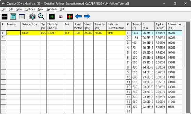
Step 4:
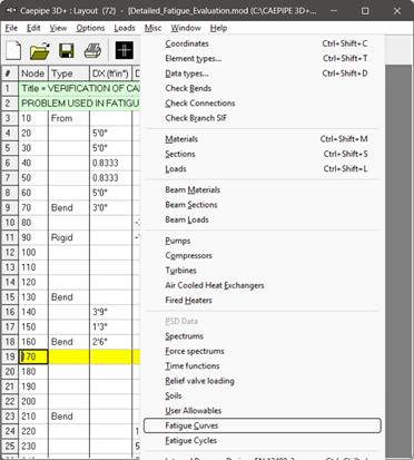
Import / Read the Fatigue Curve into CAEPIPE for Fatigue Evaluation.
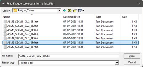
CAEPIPE is supplied with seven (7) Fatigue Curves corresponding to Figures 3-F.1 through 3-F.7 of ASME Section VIII, Division 2 (2021). These Fatigue Curves are available inside the folder “Fatigue_Curves” of CAEPIPE installation directory.
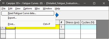
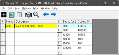
Fatigue curve corresponding to ‘Fatigue Curve for Wrought 70–30 Copper–Nickel for Temperatures not Exceeding 700°F—σys = 45 ksi’ from ASME Section VIII, Division 2 (2021)’ supplied with CAEPIPE is used for the present Fatigue Evaluation. This fatigue curve is imported into CAEPIPE by selecting the file ‘ASME_SECVIII_DIV2_3F6’ available in Fatigue Curves folder through “Layout Window > Misc > Fatigue Curves > File Menu > Read Fatigue curve data” as shown in the snapshots below.
Step 5:
Assign Fatigue Curves to the Materials through “Layout Window > Misc > Materials > Fatigue Curve Name” as shown below.
Note:
To exclude a section of the layout from fatigue analysis, the user should either create a new material or copy an existing one and leave the fatigue curve section blank. This material, with no assigned fatigue curve, can then be applied to all sections intended to be excluded from fatigue evaluation.
Step 6:
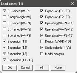
For inputting the Actual Number of Fatigue cycles, select the required Expansion load cases through “Layout Window > Loads > Load cases” as shown below.
Once the required load cases are selected, input the Actual Number of Cycles (N) as detailed above under the Section titled “Actual Number of Cycles to be Input for Detailed and Simplified Fatigue Analysis” in this tutorial for the selected Expansion load cases through “Layout Window > Misc > Fatigue Cycles” as shown below.
Note:
To exclude any load cases from fatigue analysis, the user should leave the "Number of Cycles (N)" section blank in the corresponding table.
Step 7:
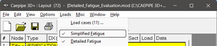
Turn ON (tick) the Simplified and Detailed Fatigue load cases through Layout Window > Loads.
Step 8:
Save the model and perform the Analysis through “Layout Window > File > Analyze”.
Step 9:
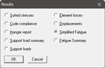
Review the Simplified Fatigue Evaluation Results by selecting the option “Simplified Fatigue” through “Results Window > Results”.
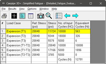
CAEPIPE uses the above computed equivalent number of full displacement cycles (Ni = 12791) to determine the Stress Range Reduction Factor (f), which is then used in computing the Expansion Allowable Stress (SA) shown under Sorted Stresses and Code Compliance results of CAEPIPE corresponding to the piping code ASME B31.1 (2024) selected for analysis.
Step 10:
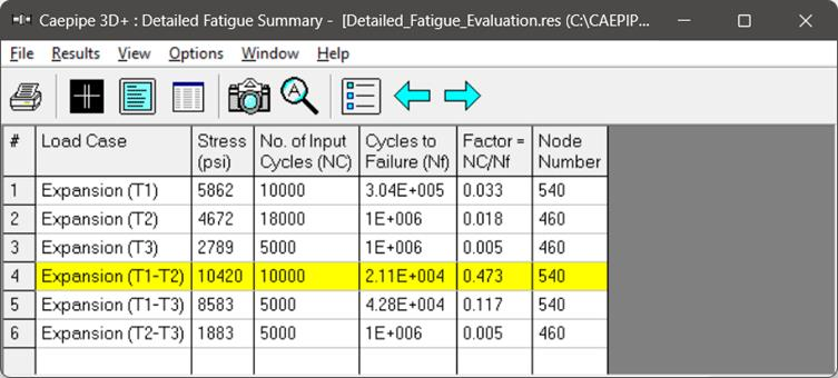
Review the Detailed Fatigue Evaluation Results by selecting “Sorted stresses”, “Code compliance”, “Elemental Forces”, or “Fatigue Summary” through “Results Window > Results” as shown below.
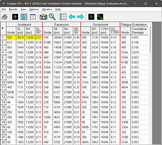
When the Detailed Fatigue Evaluation is enabled in the analysis for applicable piping codes, the following additional results will be added:
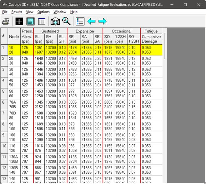
· Sorted Stresses: CAEPIPE will display additional columns under the "Fatigue Evaluation".
· Code Compliance: CAEPIPE will display additional column under the "Fatigue" section. This column will show the cumulative damage factor calculated from all the selected expansion load cases at each element, as illustrated above.
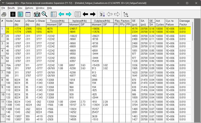
· Element Forces: CAEPIPE will display additional columns titled Actual number of cycles (Act. Cycles), Number of cycles to failure (Cyc. to Failure) and Damage Factor related to Fatigue Evaluation as shown above.
Summary:
Since the total Cumulative Damage factor at each node is less than 1.0, the stress layout is considered safe and no further modifications for the stress layout is required as per Fatigue Evaluation.