Bellows
Bellows expansion joints are flexible elements included in high temperature piping systems to absorb primarily thermal movement. A Bellows contains one or more convolutions designed to withstand the internal pressure while still flexible enough to absorb the axial, lateral and bending deflections. Before use, you should note the critical pressure at which the bellows becomes unstable. The B31.1 piping code suggests that expansion joints may be employed only “when piping bends, loops, and offsets are not able to provide adequate flexibility.” (Para. 11.5, 2010).
Usually, manufacturers of these expansion joints publish product catalogs that contain technical information about the joints you could use in your systems. The EJMA (Expansion Joint Manufacturers Association) also publishes a standards catalog with guidelines that “assist users, designers, and others in the selection and application of expansion joints for safe and reliable piping and vessel installation.”
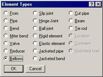
A Bellows joint is input by typing “bel” in the Type column or selecting “Bellows” from the Element Types dialog.
The Bellows dialog is shown.
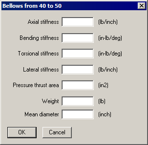
Expansion joints are mainly modeled using the above shown four types of stiffnesses – axial, bending, torsional and lateral. The required stiffness values, pressure thrust area and weight should be taken from the manufacturer’s catalog.
For a rigid stiffness (for example, torsional), enter “r” for Rigid; if highly flexible, enter 1 (lb/in.) as a minimum, to avoid dividing by zero during internal computation.
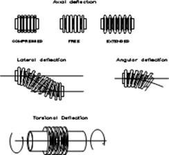
Axial: Refers to axial extension (as in cryogenic systems) or contraction (as in high-temperature systems) axially along its centerline while in operation.
Bending (angular): Refers to the bellows bending about its center point on the centerline. Bending can be in any plane that passes through the centerline.
Lateral: Refers to the direction perpendicular to the centerline of the bellows. The two ends of the bellows remain parallel to each other while their centerlines are displaced causing an offset. This direction is also called transverse or parallel offset direction.
Torsional: Usually very stiff, refers to a twisting moment at one bellows end while the other end either relatively is stationary or twists in the other direction, about the bellows centerline.
The pressure thrust area will impose a thrust load of: (pressure × thrust area), on both nodes of the bellows. Even if the bellows is tied, it is recommended that the pressure thrust area be input.
The weight is the empty weight. CAEPIPE adds the weight of the contents, insulation and additional weight internally to the empty weight.
Weight of the bellows joint is input in lbf or kgf and NOT its mass. Whenever mass is required for a calculation as in the case of forming Mass matrix for dynamic analysis, or in calculating inertia force as (mass x acceleration) for static seismic analysis, CAEPIPE internally computes the mass to be equal to (weight / g-value).
Mean diameter is the “mean” between the outer and inner diameters of any Convolution of the bellows. Since outer and inner diameters of all convolutions of the bellows are the same, the Mean diameter is the same for all convolutions of that bellows.
Pipe guides are needed adjacent to the bellows because of its inherent flexibility and the compressive loading on the adjacent pipes due to the pressure thrust of the joint. Moreover, proper guiding is necessary to direct thermal movement into the joint and prevent buckling of the line. Depending on the bellows behavior, you should place the first guide no farther than four pipe diameters from the joint. Place additional ones appropriately after studying the nearby deflections and loads. Also, consider vessel and anchor movements, which may cause a misalignment at the joint. See the topic on Expansion Joints for examples.