Local Coordinate System
CAEPIPE allows you to create your physical piping system in a mathematically equivalent 3D Cartesian coordinate space with a global origin, which is the point of intersection of three planes orthogonal to each other, with three axes commonly denoted X, Y and Z (with either of the latter two vertical).


Y Vertical Z Vertical
Once you begin creating your system from a given point (usually the global origin), you route your piping system one element at a time until you get to the end of the line(s). An element’s orientation could be different from another element’s, thereby necessitating an element’s own “elemental coordinate system,” which is commonly referred to as the Local Coordinate System (LCS), provided for the purpose of understanding the local forces and moments on each element. This system can be turned on (graphically) through the View menu > Show LCS command while you are viewing “Element Forces in Local Coordinates” in the Results window.
For a straight element (such as a pipe or a beam), the “local x” axis is along the element, from the “From” node to the “To” node. For a node location such as a guide, the local axes are based on the previous connected element. If the preceding element does not exist, the following element is used. The local y-axis and local z-axis are calculated differently depending on whether the vertical direction is Y or Z and also depending on whether the element is in the vertical direction.
The local coordinate system may be displayed graphically (for beams and guides in the input processor and for all the elements in the output processor) by selecting the “Show LCS (Local coordinate system)” command from the View menu.
In CAEPIPE, the local coordinate system is indicated by the lower-case x, y and z letters, whereas the global coordinate system is indicated by the upper-case X, Y and Z letters.
Global vertical axis is Y
Element is not Vertical
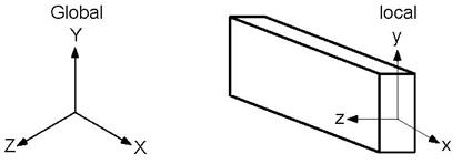
The local y-axis of the element lies in the local x - global Y plane (i.e., vertical plane) and is in the same positive direction as the global Y axis. The local z-axis is the cross product of the local x-axis and local y-axis
Element is Vertical
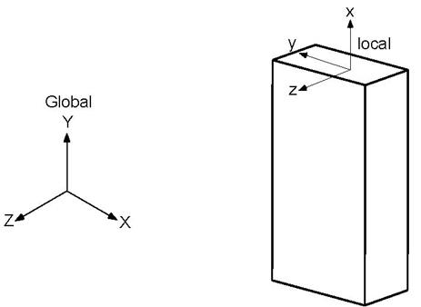
The local z-axis of the element is in the global Z direction. The local y-axis is in the global –X direction.
Global vertical axis is Z
Element is not Vertical
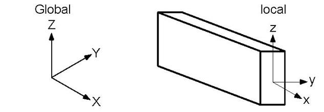
The local z-axis of the element lies in the local x - global Z plane (i.e., vertical plane) and is in the same positive direction as the global Z-axis. The local y-axis is the cross product of the local z-axis and local x-axis.
Element is Vertical
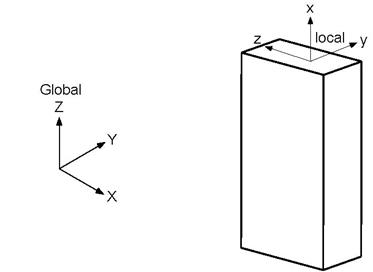
The local y-axis of the element is in the global Y direction. The local z-axis is in the global–X direction.
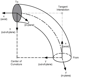
Local Coordinate System for a Bend
For a bend, at the “From” node, the local x axis is along the tangent from the “From” node to the tangent intersection point. The local y-axis is along the radius and points to the center of curvature. The local z-axis is the cross product of the local x-axis and local y-axis.
Similarly, at the “To” node, the local x-axis is along the tangent line from the tangent intersection point to the “To” node. The local y-axis is along the radius and points to the center of curvature. The local z-axis is the cross product of the local x-axis and local y-axis.
Sign Convention for Element Forces and Moments
The sign conventions for the element forces and moments in the local coordinate system follow strength of materials conventions, i.e., forces and moments at the “To” node of an element are positive if they are in the positive local axes directions of the element. On the other hand, forces and moments at the “From” node of the element are negative if they are in the positive local axes directions of the element.
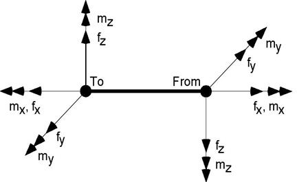
Positive sign conventions for local forces and moments are shown above at the “From” and “To” nodes of an element. Note that positive directions at the “From” node are reversed compared to the positive directions at the “To” node.
In-plane and Out-of-plane Moments
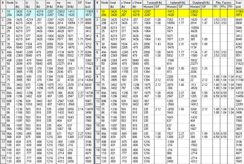
CAEPIPE outputs local moments in the form of Torsion, In-plane and Out-of-plane for a few piping analysis codes such as ASME B31.1 (2020) or later, ASME B31.3, etc.
To have graphical illustrations of the In-plane and Out-of-plane moments, shown below are the two sample CAEPIPE models created by keeping Global vertical axis as Z and Y respectively along with the following outputs.
1. Local Coordinate System (LCS) captured for different elements by turning on the option Results Window > View menu > Show LCS command while in “Element Forces in Local Coordinates”.
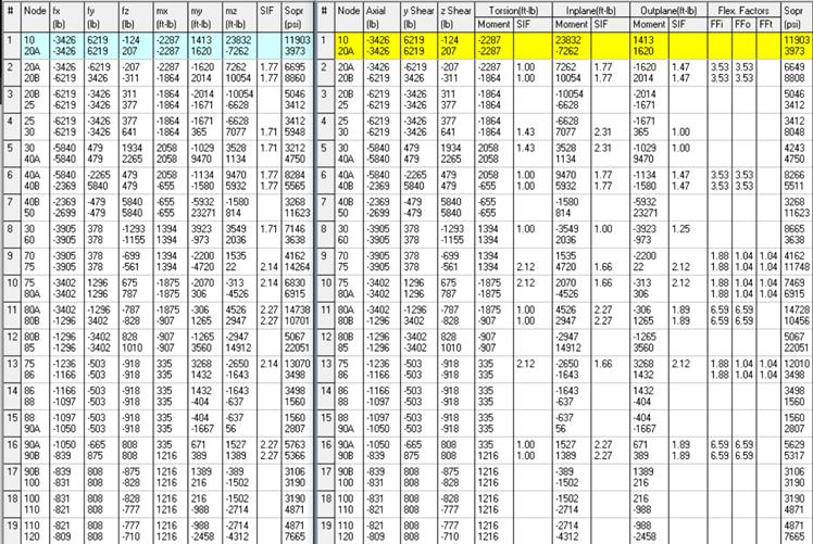
2. Local forces and moments output by CAEPIPE with piping analysis code selected as ASME B31.9, and
3. Local forces and moments output by CAEPIPE with piping analysis code as ASME B31.1.
From the graphical representation of LCS and the local forces and moments output by CAEPIPE using ASME B31.9 and ASME B31.1 codes, you may observe that the In-plane moment is about local z-axis and its corresponding rotation is in local x-y plane, and whereas the Out-of-plane moment is about local y-axis and its corresponding rotation is in local x-z plane for all element types such as Pipe, Bend, Miter, Reducer, Valve, Rigid, etc. (excepting TEEs) available in CAEPIPE.
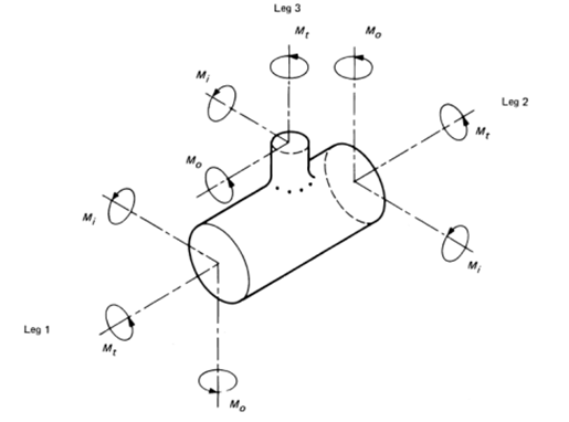
Similarly, from the LCS and the local forces and moments output by CAEPIPE using ASME B31.9 and ASME B31.1 codes, you may observe that the In-plane moment (Mi) of a Tee element is about the vector normal to the plane formed by connecting the two nodes on the Run side (Leg 1 and Leg 2) as well as a node on the Branch side (Leg 3) as shown in the figure below. Similarly, Out-of-plane moments (Mo) for the three legs of Tee are as shown below.
When Global Z Axis Vertical
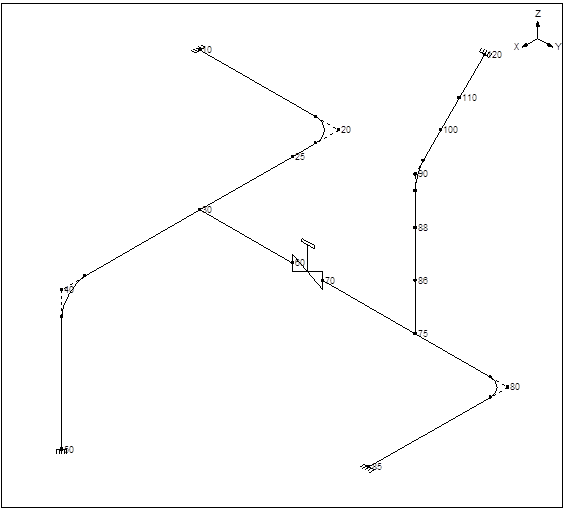
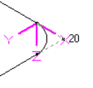
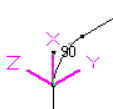
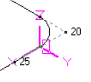
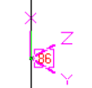
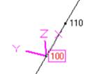
Fig. A.1 Fig. A.2 Fig. A.3 Fig. A.4 Fig. A.5
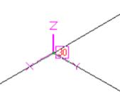
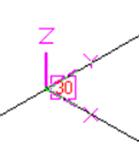
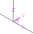
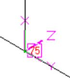
Fig. B.1 Fig. B.2 Fig. B.3 Fig. B.4
|
Fig. A.1 - Bend in Horizontal Plane
Fig. A.2 - Bend in Vertical Plane
Fig. A.3 - Pipe in Horizontal Plane
Fig. A.4 - Pipe Vertical Plane
Fig. A.5 - Pipe Skewed in 3D
|
Fig. B.1 - Tee in Horizontal Plane – Run Element
Fig. B.2 - Tee in Horizontal Plane – Branch Element
Fig. B.3 - Tee in Vertical Plane – Run Element
Fig. B.4 - Tee in Vertical Plane – Branch Element
|
ASME B31.9 Code Selected ASME B31.1 Code selected
|
Element Type
|
In-plane Moment
|
Bending in what plane?
|
Direction of +ve In-plane Moment Vector
|
Out-of-plane Moment
|
Bending in what plane?
|
Direction of +ve Out-of-plane Moment Vector
|
|
Bend (20A-20B) &
(90A-90B)
|
(mz)
|
x-y plane
|
(z axis)
|
(my)
|
x-z plane
|
(y axis)
|
|
Pipe Horizontal (20B-25), Pipe Vertical (86-88), Pipe Skewed (100-110), Reducer, etc.
|
(mz)
|
x-y plane
|
(z axis)
|
(my)
|
x-z plane
|
(y axis)
|
|
Pipe (20B-25), Pipe (86-88), Pipe Skewed (100-110), Reducer, etc.
|
(mz)
|
x-y plane
|
(z axis)
|
(my)
|
x-z plane
|
(y axis)
|
|
Pipe (20B-25), Reducer, etc.
|
(mz)
|
x-y plane
|
(z axis)
|
(my)
|
x-z plane
|
(y axis)
|
|
TEE - Run (30-40A)
|
(mz)
|
x-y plane
|
(z axis)
|
(my)
|
x-z plane
|
(y axis)
|
|
TEE - Branch (30-60)
|
(mz)
|
x-y plane
|
(z axis)
|
(my)
|
x-z plane
|
(y axis)
|
|
TEE - Run (75-80A)
|
(my)
|
x-z plane
|
(y axis)
|
(mz)
|
x-y plane
|
(z axis)
|
|
TEE - Branch (75-90A)
|
(mz)
|
x-y plane
|
(z axis)
|
(my)
|
x-z plane
|
(y axis)
|
|
The definition summarized in the above table can be verified by comparing the local moment values output in the form of In-plane and Out-of-plane by CAEPIPE for ASME B31.1 code against the local moments output in the form of mx, my and mz by CAEPIPE for ASME B31.9 code.
| ||||||
When Global Y Axis Vertical
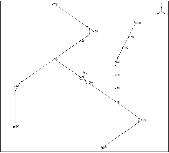
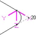
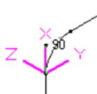
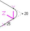
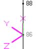
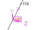
Fig. C.1 Fig. C.2 Fig. C.3 Fig. C.4 Fig. C.5
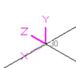
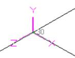
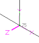
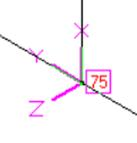
Fig. D.1 Fig. D.2 Fig. D.3 Fig. D.4
|
Fig. C.1 - Bend in Horizontal Plane
Fig. C.2 - Bend in Vertical Plane
Fig. C.3 - Pipe in Horizontal Plane
Fig. C.4 - Pipe Vertical Plane
Fig. C.5 - Pipe Skewed in 3D
|
Fig. D.1 - Tee in Horizontal Plane – Run Element
Fig. D.2 - Tee in Horizontal Plane – Branch Element
Fig. D.3 - Tee in Vertical Plane – Run Element
Fig. D.4 - Tee in Vertical Plane – Branch Element
|
ASME B31.9 Code Selected ASME B31.1 Code selected
|
Element Type
|
In-plane Moment
|
Bending in what plane?
|
Direction of +ve In-plane Moment Vector
|
Out-of-plane Moment
|
Bending in what plane?
|
Direction of +ve Out-of-plane Moment Vector
|
|
Bend (20A-20B) &
(90A-90B)
|
(mz)
|
x-y plane
|
(z axis)
|
(my)
|
x-z plane
|
(y axis)
|
|
Pipe Horizontal (20B-25), Pipe (86-88), Pipe Vertical (86-88), Pipe Skewed (100-110), Reducer, etc.
|
(mz)
|
x-y plane
|
(z axis)
|
(my)
|
x-z plane
|
(y axis)
|
|
TEE - Run (30-40A)
|
(my)
|
x-z plane
|
(y axis)
|
(mz)
|
x-y plane
|
(z axis)
|
|
TEE - Branch (30-60)
|
(my)
|
x-z plane
|
(y axis)
|
(mz)
|
x-y plane
|
(z axis)
|
|
TEE - Run (75-80A)
|
(mz)
|
x-y plane
|
(z axis)
|
(my)
|
x-z plane
|
(y axis)
|
|
TEE - Branch (75-90A)
|
(mz)
|
x-y plane
|
(z axis)
|
(my)
|
x-z plane
|
(y axis)
|
|
The definition summarized in the above table can be verified by comparing the local moment values output in the form of In-plane and Out-of-plane by CAEPIPE for ASME B31.1 code against the local moments output in the form of mx, my and mz by CAEPIPE for ASME B31.9 code.
| ||||||
Summary:
From the above illustrations, you may note the following.
1. For an element, the “local x” axis is always along the element, from the “From” node to the “To” node. The local y-axis and local z-axis are calculated differently depending on whether the vertical direction is Y or Z and also depending on whether the element is in the vertical direction. Refer to the Section titled “Local Coordinate System” given above for details on how CAEPIPE computes local y-axis and z-axis for an element.
2. Local Coordinate System (LCS) of an element can be seen (turned on) graphically through the View menu > Show LCS command while you are viewing “Element Forces in Local Coordinates” in the Results window.
3. For all elements excepting Tees, irrespective of whether the element is horizontal / vertical / inclined (skewed in 3D) or whether the Global vertical axis is Y or Z, the In-plane moment is always about the local z-axis with its +ve direction along local +z axis and its corresponding rotation is in the local x-y plane; whereas, the Out-of-plane moment is always about local y-axis with its +ve direction along local +y axis and its corresponding rotation is in the local x-z plane.
4. For TEEs, the vectors for the In-plane moments (Mi) for the three legs of Tee are normal to the plane formed by connecting two nodes on the Run side (Leg 1 and Leg 2) as well as a node on the Branch side (Leg 3) as shown in the figure above. Similarly, the vectors for the Out-of-plane moments (Mo) for the three legs of Tee are as shown above.
5. Local x, y and z axes computed internally by CAEPIPE for an element (as defined in the Section titled “Local Coordinates System” given above) can be observed by inputting the “From” and “To” coordinates of that element in the excel macro that is available in the link www.sstusa.com/downloads/GCS_LCS.xlsx. This macro is used for computing Local forces and moments from Global forces and moments.