Software Solutions
- CAEPIPE 3D+
- dataTRANSLATORS
- checkSTRESS
- HOTclash
- PEXit
- Pricing Request
- Download CAEPIPE 3D+
- Download Free Evaluation
- Download Free Review Module
- Customer Support
Engineering Services
- Design and Engineering
- INFOplant™ System
- Engineering Management
- List of Projects
- Project Gallery
- Project Videos
Learn More
Company Information
Tips April - June 2003
Flanges - Commentary
Part 1
There are multiple questions regarding how flanges should be considered in computer-aided analyses. First, it is important to understand that flange failures do not result in pipe ruptures, rather a leak is often considered a flange "failure," especially if the contents are hazardous. A B31.1 Interpretation in the late 1990's sought to clarify this, and while there was general agreement to a statement that would suggest that flanges don't normally break, the Interpretation failed to be approved for publication because the B31.1 Code did not already say this in some manner. [In general, ASME Interpretations are intended to only address how a code is currently written, not how the committees wish it were written.]
Further, the ASME B31 Codes, through the early 2000's, have done little to suggest how flanges should be considered. This, to an extent, is an indication that flanges are not much of a problem because ASME Codes are safety codes and provide rules or cautionary notes to guard against practices known to be unsafe.
Contributing to the problem is that the ASME Codes, particularly the non-Nuclear codes, are currently written for hand computational (i.e., simplified), not computer-aided, methodologies and are not likely to change soon. An acknowledged motive for simplified rules is the desire for the widest possible acceptance and appropriate application of the rules, whereas the more complicated the rules, the more likely misunderstandings and misapplications will arise. And determining the acceptability of a flange is a relatively complicated problem, which based on experience may not be a significant safety issue, except perhaps in the case that it is desirable to avoid leakage (such as in B31.3 Category M fluid service where the contents are considered very hazardous).
Another significant problem is how ASME flange acceptance data is currently provided. A less than careful reading of B16.5 (Pipe Flanges and Flanged Fittings, NPS 1/2 through NPS 24) would lead one to believe that merely knowing the pressure and temperature (and material) of a flange would be sufficient to select the proper Flange Class, e.g., Class 150, Class 300, Class 600, etc. Notice the word Class is used here to identify the flange, and not 150 lb, 300 lb, 600 lb, etc. These latter "identifiers" are often used to reference flanges, but they can lead to some confusion. While there is somewhat of a correlation between working pressure and Class at about 825 degF for more common materials, this is not a consistent correlation for all materials and flange Classes (notably Class 150 flanges).
But from a careful reading of B16.5 - 2001, Para. 2.4, one can discover that in addition to pressures and temperatures the "forces and moments developed in the connected piping" must be taken into consideration. Another authoritative set of flange rules exist in the ASME BPV Section VIII, Div. 1, Appendix 2 which also requires the external forces and moments on the flange to be considered.
The ASME Nuclear Codes do provide some conservative guidance in paras. NB/NC/ND-3658 which have been incorporated into Caepipe and other piping analysis programs. In the current nuclear codes, equations for an "effective" flange design pressure are provided converting external moments into an equivalent pressure which is then added to the system design pressure. However, it must be pointed out that flanges which can accommodate this "effective" flange design pressure may still leak under some coincident operating and environmental conditions. What can be said of flanges which can accommodate the "effective" nuclear flange design pressure, if properly manufactured and installed and excepting the gasket, that all components of the flange (the flange itself and appropriate bolting) should not exceed code allowable stresses for base material and bolting.
There are at present no published analytic methods that will assure that flange leakage will not occur. B31.1 (see Table 112) and SC VIII, Div. 1, Appendix 2 have some guidance that will help the designer with materials, flange types, bolting, and gaskets but the assurance that a selected flange configuration will not leak is beyond these sources. A major source of uncertainty is the flange gasketing. Gasket manufacturers often have guidance on their product's proper installation and may have performance data, based on testing, as well. If the assurance that no leakage will occur is required, then, short of the designer performing testing, working with a reputable gasket manufacturer will be necessary.
How to interpret CAEPIPE Flange reports - Read next month's tip (given below).
Author: Mr. Ron Haupt, P. E., of Pressure Piping Engineering (www.ppea.net) is a member of several piping code committees (B31, B31.1, B31.3, BPTCS, and others). He consults with us in the capacity of Nuclear QA Manager.
Flanges - Commentary
Part 2
Continued from Part 1 above
With regard to the Flange Report output in Caepipe, the program input includes the piping system design pressure and temperature, B16.5 class, and flange gasket diameter. Using the conservative nuclear code formulations, an "effective" flange design pressure is calculated and compared to the B16.5 flange pressure-temperature rating for the flange material. Where the ratio of the "effective" design pressure divided by the B16.5 pressure-temperature is greater than 1.0, the flange is "flagged." (Caepipe, in addition to determining an equivalent pressure from external moments, also includes in the equivalent pressure calculation an axial force term based on similar terms.)
When a flange is "flagged," the designer should review the piping system design pressure and temperature against the B16.5 pressure-temperature ratings. If the B16.5 ratings are exceeded then a heavier flange is required. If the B16.5 ratings are not exceeded, then the external moments and source of those moments should be reviewed. Additional supports or heavier flanges may be necessary if the moment stresses exceed more than about 1/3 of the allowable stress. Additional supports or heavier flanges may not be necessary or higher moment stresses may be permitted if the contents of the pipe are benign or pressures and temperatures are low or the source of the moment is an infrequent event.
Author: Mr. Ron Haupt, P. E., of Pressure Piping Engineering (www.ppea.net) is a member of several piping code committees (B31, B31.1, B31.3, BPTCS, and others). He consults with us in the capacity of Nuclear QA Manager.
How to Duplicate Repetitive Input Information
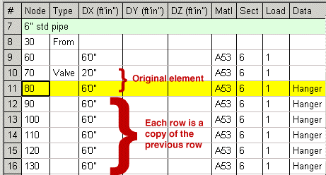
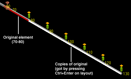
This is another handy feature that increases your productivity. For rows that repeat themselves (element, offsets, material/section/load, data item), this is a time saver. In the example below, each row between 12 through 16 is a copy of the previous row. So, starting on row 12, simply press Ctrl+Enter on each new row.
This feature is useful in modeling pipe racks or straight runs of pipe. Simply input all data in a row and press Ctrl+Enter on the new empty row to duplicate the previous row's information. The node number is automatically incremented.
A Location/Comment/Hydrotest row cannot be duplicated. Neither can an inserted row between two existing rows. This command works only on new empty rows at the end of the model. If you press Ctrl+Enter right after a Location/Comment/Hydrotest row. CAEPIPE will duplicate the row before the Location/Comment/Hydrotest row.
So, how many fewer keystrokes did we need? Too many to count!


