Software Solutions
- CAEPIPE 3D+
- dataTRANSLATORS
- checkSTRESS
- HOTclash
- PEXit
- Pricing Request
- Download CAEPIPE 3D+
- Download Free Evaluation
- Download Free Review Module
- Customer Support
Engineering Services
- Design and Engineering
- INFOplant™ System
- Engineering Management
- List of Projects
- Project Gallery
- Project Videos
Learn More
Company Information
Tips April - June 2004
Liberal Allowable Stresses Problem
Question: Why doesn't the number for SA tally with hand calculation at a branch node 55 when "Use liberal allowable stresses" option is checked?
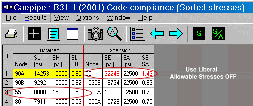
Reply: First, let us see what we have at the node when Liberal Allowable Stresses option is turned OFF. See first fig.
The numbers shown for node 55 are:
SL = 8000 psi SH = 15000 psi SE = 32246 psi SA = 22500 psi
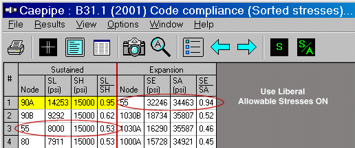
Now, let us see what we have at the node when Liberal Allowable Stresses option is turned ON. See second fig.
The numbers shown for node 55 are:
SL = 8000 psi SH = 15000 psi SE = 32246 psi SA = 34463 psi
When we increase SA in the first case (22500 psi) by f(Sh- SL), because that is how the code wants you to account for liberal allowable stresses, we get SA = 29500 psi (22500+[15000-8000]). However, CAEPIPE displays 34463 psi. That is a difference of 11963 psi! (assume f = 1 here).
So, the real question is: Where did the 11963 psi (34463 psi — 32246 psi) come from?
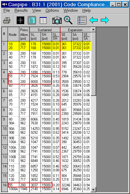
Let us examine the model further. 55 is a branch node. So, we will have at least three elements coming together - two pipe runs and one branch run. The two pipe runs are: 50 to 55, 55 to 60, and the branch is from 55 to 1000.
So, in the code compliance screen, we need to see which one of these THREE elements (# 4, 5, and 16 in the last figure) gives us the most difference for (Sh - SL). Upon examination, we see that the element 55 to 1000 has an SL of 3037 psi, which gives rise to the most difference of 15000 - 3037 = 11963 psi.


Hot Modulus vs. Cold Modulus Effect on Loads and Stresses
Question: Why do sustained stresses and the sustained support loads change when a “sustained load” analysis is done once with E cold (Use modulus at reference temperature option) and a second time with E hot (Use temperature dependent modulus option)?
Note: This option can be found under Layout window > menu: Options > Analysis > Temperature > Elastic modulus.
Reply: Value of E decreases with increasing temperature. So, when E cold is opted, CAEPIPE calculates stiffness matrix [K] using E value corresponding to reference temperature. On the other hand, when E hot is opted, [K] is calculated using E value at the temperature T1 specified under load. Since E decreases with increasing temperature, the structure becomes “more flexible” with increasing temperature, which means loads get redistributed within the piping system resulting in changes to pipe stresses and support loads. Normally, thermal pipe stress and support loads should decrease with increasing temperature as the structure gets more flexible; whereas, sustained and occasional load stresses and the corresponding support loads may increase or decrease depending on the redistribution of sustained and occasional loads within the piping system.
The above discussion is true for a linear system with nofriction and no gaps (i.e., no nonlinearities).
Once nonlinearities are present, even thermal stresses and support loads may increase or decrease depending on the change in the “status of gaps and friction” when E is changed from “cold” to “hot” value.
Such physical aspects of CAEPIPE usage are covered in our piping seminars. Contact us for more details.
Hydrostatic Test Loadcase
Question: B31.3 piping code suggests that nominal stresses be calculated for the hydrotest case. But, I do not see CAEPIPE output nominal stresses. It seems to output only support loads, element forces and displacements.
Note: A hydrotest case can be input using Hydrotest from the element type dialog or by pressing "h" on an empty row in the Layout window.After marking the different areas of the model, check Hydrotest under Loads menu>Loadcases in layout.
Reply: Stress analysts mostly ascertain whether they need to add temporary supports for the designed system during hydrotest (typically may only be considered if the pipe is a large diameter, low pressure gas line of some sort - note in some cases hydrostatic head may add to the hydrotest pressures). Nominal hoop stresses are usually calculated only to the extent of determining if the required test pressure should be considered a candidate for reduction, in accordance with B31.3, para. 345.2.1(a). CAEPIPE does not include any direct nominal hoop stress output for hydrotest case, but this may be done with a hand calculation using the "Barlow" equation, i.e., S(nom) = P(test)*D(nom)/(2*t(nom)) . For the hydrotest case, CAEPIPE displays only support loads, element forces and displacements. But, if you are interested in calculating longitudinal stresses, the sustained load (S(L)) case may be conservatively used as follows.
1. Make sure that you do not include corrosion allowance and mill tolerance in your sections definition so that CAEPIPE uses nominal values for section modulus calculations.
2. Change material allowables at T = 70 deg. F to show yield strengths of the materials at ambient (test) temperature.
3. Calculate input hydrotest pressure = 1.5*P(design)*S(y,ambient)/S(y,design), see B31.3, para. 345.4.2(b).
4. Since the S(L) equation includes the stress intensification factors (SIFs) due to the term 0.75i, you will see higher stresses than their nominal counterparts, or to see only nominal stresses you could input "User SIFs" to reduce all the internally calculated SIFs to unity.

