
Software Solutions
- CAEPIPE
- CAEPIPE 3D+
- checkSTRESS
- dataTRANSLATORS
- HOTclash
- PEXit
- Pricing Request
- Download Free Evaluation
- Download CAEPIPE 3D+
- Download Free Review Module
- Customer Support
Engineering Services
- Design and Engineering
- INFOplant™ System
- Engineering Management
- List of Projects
- Project Gallery
- Project Videos
Learn More
Company Information
CADMATIC
Input File: Cadmatic Neutral File (.n)
Output File: CAEPIPE Model File (.mbf)
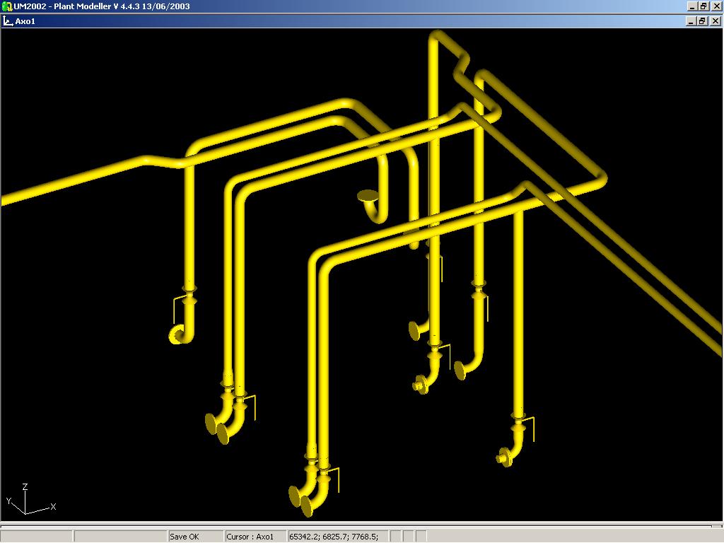
PD2CAEPIPE™, the Plant Design-to-CAEPIPE Interface, is a stand-alone program for transferring pipe geometry including section properties from ELOMATIC’s CADMATIC to SST’s Pipe Stress Analysis software CAEPIPE.
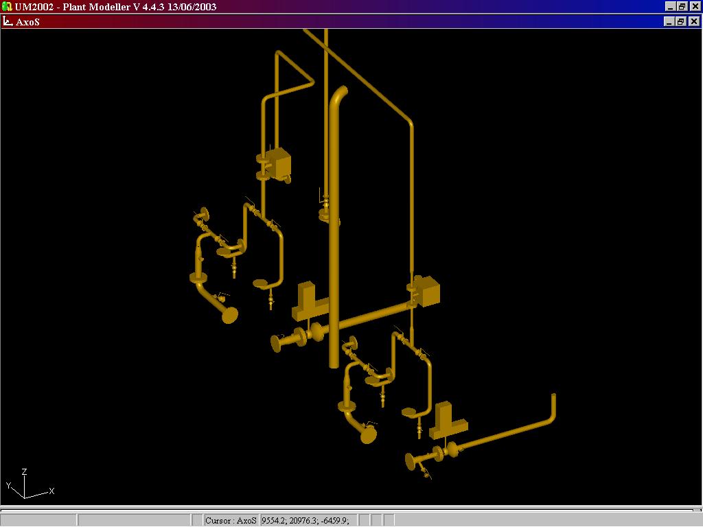
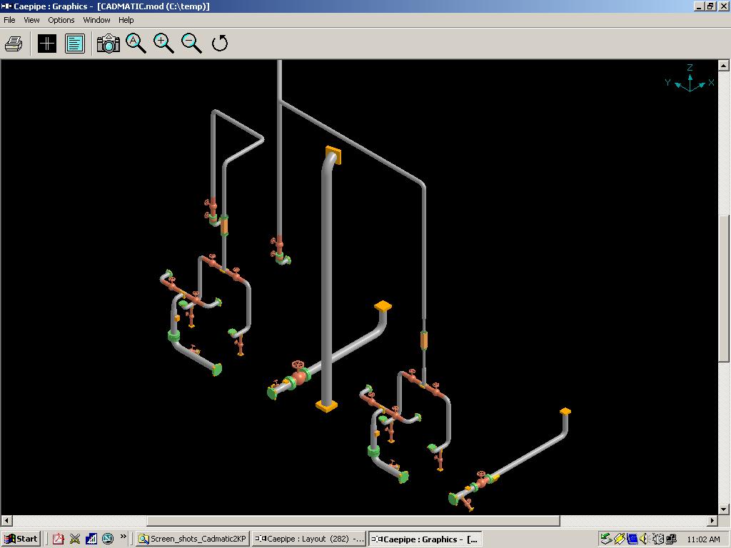
PD2CAEPIPE Interface converts the 3D piping model in CADMATIC format into an intermediate neutral file. CADMATIC material specifications used are then compared against the Mapping Database that are provided along with the PD2CAEPIPE Interface to identify the corresponding CAEPIPE materials. These materials are merged with the intermediate neutral file to generate the CAEPIPE Batch Input file (.mbf), which is, in turn, converted to the input file .mod in binary format by CAEPIPE.
The execution sequence is as follows.
The interface consists of two parts.
1. CSL Macro to identify the Pipelines in CADMATIC and to create an intermediate neutral file.
2. PD2KP.EXE file to convert the intermediate neutral file to batch input of CAEPIPE.
Salient Features
- Uses forms and menus to input the name of the neutral file and to identify the pipelines in CADMATIC model to be added in the network for transferring to CAEPIPE.
- Transfers the geometry of the pipe(s) routed in CADMATIC to CAEPIPE.
- Interface does not require that all pipelines be stored under one system. They can even be part of different systems.
- Transfers pipe section properties and name these sections automatically in CAEPIPE.
- Transfers temperature and pressure of the pipeline assigned in CADMATIC tag opT and user defined CADMATIC tag opP as TEMP and PRES respectively in CAEPIPE. Each such unique combination of temperature and pressure will be treated as a load name in CAEPIPE.
- Ignores CADMATIC slave part GASKET in CAEPIPE for stress analysis. However, the interface takes into consideration the implied length of these components for the purpose of nodal geometry.
- Treats control valves as valve element in CAEPIPE.
- Transfers supports modeled in CADMATIC to CAEPIPE using an user defined CADMATIC tag sty assigned to the components connecting the pipe and the pipe support such as U-clamp, O-clamp, etc., at each support location (i.e. standard component inserted as on-line component in the pipeline at support location in CADMATIC). The data file "SUPPTYP.DB" lists the various support codes that need to be stored in the user defined CADMATIC tag "sty to transfer support type to CAEPIPE.
- Transfers multi-way components like 3-way valve, 4-way valve and cross with a simple node point at the origin of these elements.
- Allows the user to choose the vertical direction for CAEPIPE i.e., the vertical direction in CADMATIC (Z) can be made as either 'Y' or 'Z' in CAEPIPE.