
Software Solutions
- CAEPIPE 3D+
- dataTRANSLATORS
- checkSTRESS
- HOTclash
- PEXit
- Pricing Request
- Download CAEPIPE 3D+
- Download Free Evaluation
- Download Free Review Module
- Customer Support
Engineering Services
- Design and Engineering
- INFOplant™ System
- Engineering Management
- List of Projects
- Project Gallery
- Project Videos
Learn More
Company Information
Tips July - September 2000
How to Improve Your Efficiency Using CAEPIPE?
Part 4b - The "Generate" Command - More examples
Part 4a introduced the Generate command (under the Edit menu in Layout) with two examples.
This part will finish this topic by providing two more examples.
For those of you who have not read Part 4a, this command lets you duplicate or copy existing data in the Layout window (spreadsheet). Examples could be copying existing expansion loops, piperacks, creating multiple segments of uniform sloped piping, or buried piping, or stacks of piping, among other creative uses.
Let the pictures tell the story!
Third example: Expansion loop
Objective is to create one or more set(s) of an existing section of piping (in this case, an expansion loop). As before, create one, and let Generate do the rest! See figures below. The first one is "before" and the next one is "after" the Generate command. In the graphics figure below, the numbers in cyan color (3 4, 5...) are row numbers that correspond with the rows in the Layout window.
We want to duplicate the section of piping from node 20 (bend) to node 60 (end of section). Let us make three copies.
The "Increase node numbers by" field needs to be understood. Essentially, we want to have the bend at node 20 repeat after node 60. So, the new bend should be node 70. So, the difference in the node numbers is 50 (70-20) which is the input for "Increase node numbers by" field.
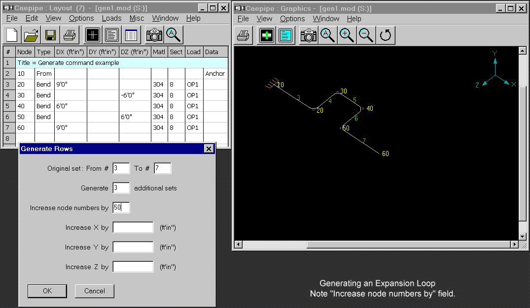
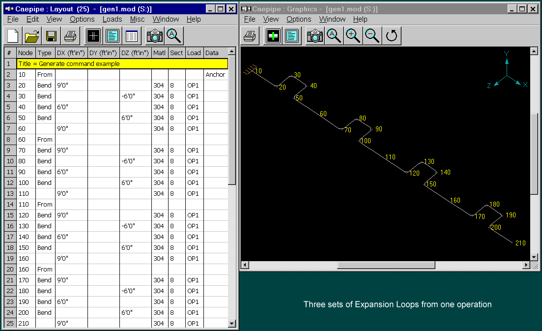
A few of the node numbers will be duplicated such as node 60. The new loop starts "From" node 60. This is the same as continuing from the previous node 60.
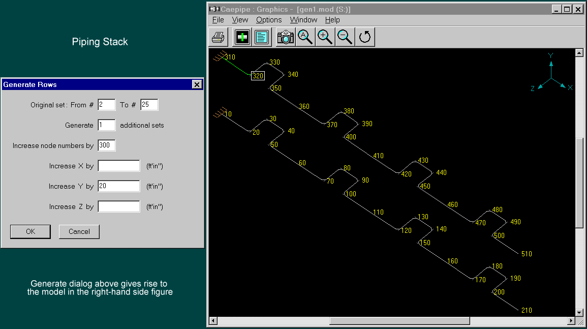
Fourth example: Piping Stack
Starting from the figure above (node 10 to node 210), say we wanted to duplicate this whole length of piping but above it, as a stack; As if we need to "bodily lift" the bottom one. That is precisely what the Generate command does. The "before" figure is the figure above. The result of the Generate command is shown below. The piping from node 310 through node 510 was generated in one operation as shown by the Generate dialog below.
That is it for the Generate command. You may want to play with it to find more creative uses.
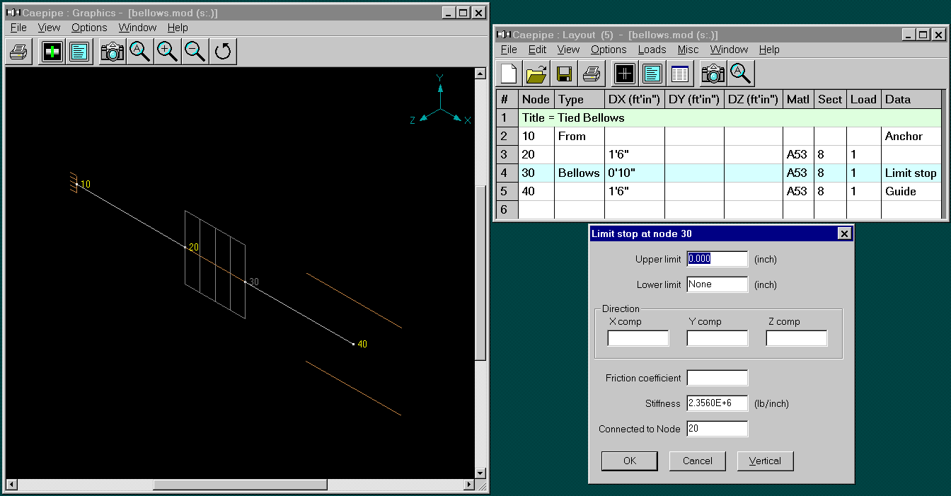
Modeling Tied Bellows
Tie rods are used in expansion joints to absorb the thermal growth in piping and eliminate pressure thrust. Tie rods are used on a number of expansion joint types.
How to model in CAEPIPE:
A bellows expansion joint may be modeled by typing "bel" in the Type column and entering the requisite information (see manufacturer's catalog for the technical data).
Tie rods symmetrically placed around the bellows may be simulated by using one limit stop (press "L" in the Data column) that connects the two bellows nodes ("From" and "To" nodes). This limit stop must act as a "tension only" element, i.e., have stiffness when in tension and no stiffness when in compression. The limit stop is in "tension" when the two nodes (limit stop node and the connected node) are moving away from each other which corresponds to the Upper Limit of the limit stop. Hence, the Upper Limit should be zero and the Lower Limit should be None.
Note that the stiffness for the limit stop is the collective stiffness of the four symmetrically placed tie rods. The data for a tie rod in this example are: E=30x10^6 psi, A=(pi)xd^2/4, (d=0.5"), and L=10". Stiffness = 4 x (AE/L).
Example: Please examine the data for the limit stop in the figure below.
Commentary on Stress Intensification Factors (SIF) - by Ron Haupt