
Software Solutions
- CAEPIPE 3D+
- dataTRANSLATORS
- checkSTRESS
- HOTclash
- PEXit
- Pricing Request
- Download CAEPIPE 3D+
- Download Free Evaluation
- Download Free Review Module
- Customer Support
Engineering Services
- Design and Engineering
- INFOplant™ System
- Engineering Management
- List of Projects
- Project Gallery
- Project Videos
Learn More
Company Information
Tips July - September 2001
How to Export Data to a Spreadsheet from CAEPIPE
Did you know you can use the menu: File > Export command in the List or the Results window to export the following items to a text file in Comma Separated Values (csv) format? These data can be read by spreadsheets (such as MS-Excel) and plotted.
The data items that CAEPIPE presently exports are:
- Materials
- Spectrums
- Time functions
- Time history results
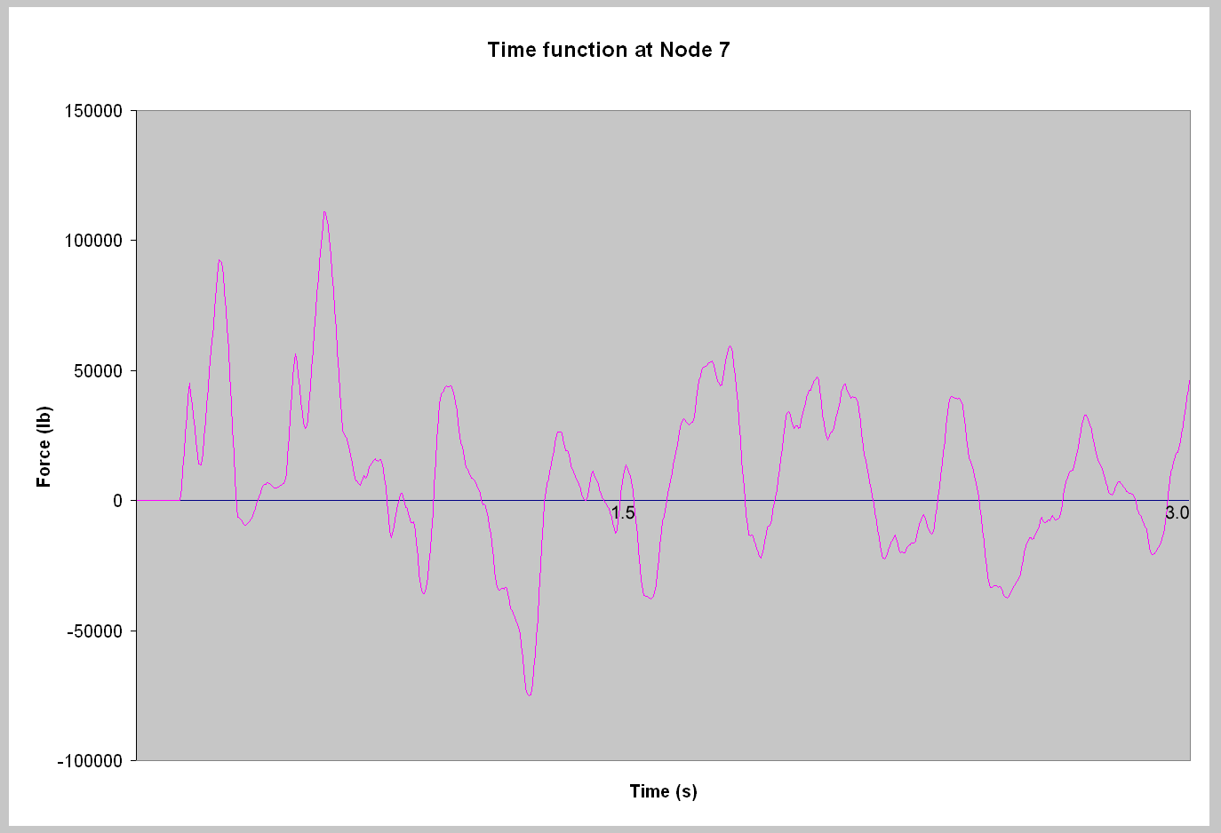
A sample time function is charted below:
When To Use Liberal Allowable Stresses
Question: "When should Liberal Allowable stresses (in B31.1) be used?"
Reply: Perhaps the term "liberal allowable" is not the best to describe the allowable. The allowable stress in B31.1 Eq. 13, i.e., S(A) + f(S(h) - S(L)), can be used anytime. The only prerequisite is knowing the S(L) stresses, which will only be the case after the supports are known or implicit. The Eq. 1 allowable stress, S(A), is the allowable stress traditionally used in the flexibility analysis when no supports other than the equipment anchors are known. The flexibility analysis is used to determine whether the layout of piping between the equipment anchors is adequate. The displacements determined in the flexibility analysis will allow the designer to devise the pipe weight supports to interfere with the flexibility of the pipe as little as possible, i.e., the designer will use rigid supports where the piping does not move much, use variable springs where the piping moves a small amount (most typically 1/4" to 4"), and use constant springs where the movement is great (again, typically over 4"). For lateral loads the same concept as used for the pipe weight supports is used for the lateral supports, i.e., if lateral displacements are small, rigid supports may be used, for larger lateral movements, gapped or shock suppressor supports are used (although shock suppressor supports require considerable maintenance attention and in the long run are usually not preferable to gapped supports).
Author: Mr. Ron Haupt, P. E., of Pressure Piping Engineering (www.ppea.net) is a member of several piping code committees (B31, B31.1, B31.3, BPTCS, and others). He consults with us in the capacity of Nuclear QA Manager.
Understanding Pipe Forces in Local Coordinate System in CAEPIPE
The sign conventions for element forces and moments follow Strength of Materials sign conventions (see Introduction to Mechanics of Solids by Egor P. Popov or Strength of Materials by F. R. Shanley). The forces and moments acting on the element in local coordinates are positive if they are in the positive directions at the To node. They are also positive if they are in the negative directions at the From node. Otherwise they are negative. An example of an element in tension is shown below:
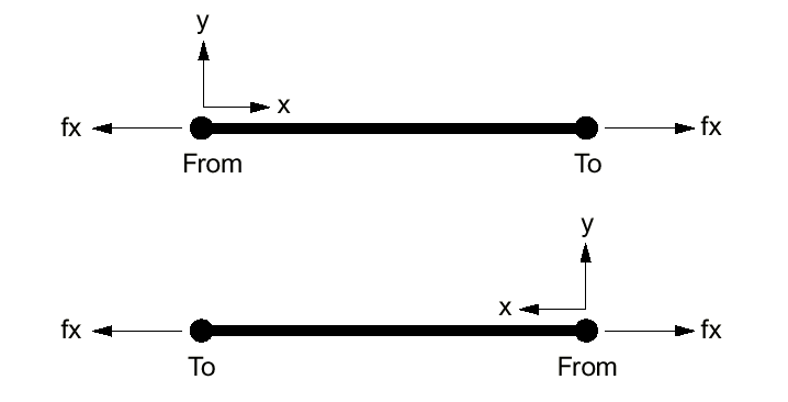
In the above example, with the element going from left to right, the force fx at the To node is positive in the local coordinate system, therefore the local axial force is positive. The force fx at the From node is negative in the local coordinate system, therefore again local axial force is positive.
In the bottom example, with the element going from right to left, the force fx at the To node is positive in the local coordinate system, therefore the local axial force is positive. The force fx at the From node is negative in the local coordinate system, therefore again local axial force is positive.
(Also see Element Forces in CAEPIPE)