
Software Solutions
- CAEPIPE 3D+
- dataTRANSLATORS
- checkSTRESS
- HOTclash
- PEXit
- Pricing Request
- Download CAEPIPE 3D+
- Download Free Evaluation
- Download Free Review Module
- Customer Support
Engineering Services
- Design and Engineering
- INFOplant™ System
- Engineering Management
- List of Projects
- Project Gallery
- Project Videos
Learn More
Company Information
Tips July - September 2009
High Flange Loads
Suggestions for dealing with high flange pressure to allowable ratios
In the CAEPIPE results window, when you click on Flange report, you are shown the loads at each flange location for the operating case (W+P+T).
The "equivalent" flange pressure is the sum of three terms in the equation shown in CAEPIPE user's manual (v5.1J, page 162). The last column shows a ratio of this equivalent flange pressure to a user-input allowable pressure. If this ratio is more than 1.0, then CAEPIPE shows the ratio in red.
There are several ways of dealing with a high ratio, as given below.
- Ensure that you input an allowable pressure for the flange by looking up B16.5 or a similar code (as a function of design temperature and pressure).
- The eqn. from CAEPIPE manual (op.cit) is generally regarded as a conservative eqn. Being so, you can discard the axial stress term in it to arrive at a new "eqv. flange pressure." This should be done outside CAEPIPE, maybe in a spreadsheet.
- If the fluid carried within the pipe is non-hazardous, you can increase the allowable pressure by 10-20%, depending on your judgment.
- Since a flange is highly unlikely to fail by collapse, one of the key ideas of the flange report is to "quantify" the tendency of a flange to pry open and spill its contents. Engineering judgment will play an important role in interpreting this report. The method, though crude, is the accepted one in the industry.
- If none of the above work, then you will have to reduce the bending moment at those flange locations. Most of the times, they are coming from the expansion case. But, be sure to examine all load cases.
To read a general background on flanges, see what one ASME B31 code committee member has to say:
Flanges-Commentary-Part 1
Flanges-Commentary-Part 2
High Flange Loads
User Question: I see wind load results even when I have turned Wind load off. What am I doing wrong?
Reply: Upon examining the input data closely, we found this input (See image below). Can you identify what is wrong with the data in the boxed area?
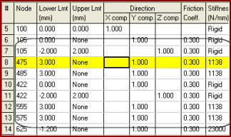
This model has limit stops at node 475, 485, 555 and 575 with Upper Limit as "None" and Lower Limit as "3.00 mm". This means that the pipes are being pushed to 3 mm in the +Y direction. But, in CAEPIPE, the UL (upper limit) has to be algebraically greater than the LL (lower limit).
This input error results in a movement of 3 mm, which generates forces and moments internally irrespective of whether Wind (or any other load) is being applied or not, It may be considered as a kind of a "preload." The solution, of course, will be to replace the Lower Limit of 3 mm with -3 mm (or 0 mm, if that is what the designer intended) such that it produces expected results.