
Software Solutions
- CAEPIPE
- CAEPIPE 3D+
- checkSTRESS
- dataTRANSLATORS
- HOTclash
- PEXit
- Pricing Request
- Download Free Evaluation
- Download CAEPIPE 3D+
- Download Free Review Module
- Customer Support
Engineering Services
- Design and Engineering
- INFOplant™ System
- Engineering Management
- List of Projects
- Project Gallery
- Project Videos
Learn More
Company Information
Tips July - September 1999
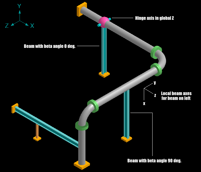
Rendering of beams
Starting version 5.01B, beams can be rendered by specifying the depth and width of the beam section. So too can hinge joints with axis specified.
In the figure below, notice the two beams, one with a beta angle of 90 deg. and how it is shown differently from the beam which has no angle specified. The beta angle is used to define the orientation of the beam local axes. Observe the local axes for the beam (that applies to the beam with a beta angle of 90 deg.).
The local coordinate system for the beam can be shown on graphics in single line mode (select List>Beams, List Window>View menu>Show LCS).
A Few Tips for Flexible Layouts
In laying out hot piping, one should consider the following:
1. The expansion of turbines, towers, heat exchangers, etc., must be added to the pipe expansion.
2. A heat exchanger is generally fixed at one end, and free to slide at the other.
3. Long radius elbows are more flexible than five diameter bends. The elbows produce lower forces but higher local stresses because of the flattening of a curved member when it flexes. The five diameter bend flattens less and therefore produces higher forces but lower local stresses. These local stresses are in the bend or elbow itself.
4. Pumps, turbines and compressors must have low forces on them as required by the manufacturer and in compliance with API/NEMA. If the stress in the piping adjacent to the equipment is limited to 5000 psi, the forces will generally be acceptable.
5. Dead weight of piping must in most cases be carried by independent supports and not by the pump, turbine or compressor. In the case of heat exchangers and vessels and other non-rotating equipment, some of the piping dead weight loads may be transferred to the nozzles but the designer must check with the equipment designer first.
6. Always run a line with the thought as to how it will be supported. Lines should be grouped whenever possible. If a line needs to be rerouted for better support, this should be done.
7. Cold spring is not the answer to lowering stresses in overstressed piping. Piping codes do not permit this. They allow only a one-third reduction in forces and bending moments if the line is cut short by 50% of its total expansion.
The above tips are excerpted from SST 101: Piping Design and Analysis Seminar Notes.
Placing Dead Weight Supports
This tip will give you a guideline for locating the supports in your piping system.
- Locate dead weight supports using recommended spacing from the code (B31 etc.).
- Consider existing support points.
- Decrease span by half off equipment.
- Decrease span for concentrated loads.
- Support concentrated loads.
- Support offset loads.
- Decrease span for extra lagging or insulation.
- Locate supports at changes in direction (no overhung corners, top or bottom of risers).
- Select type (rigid, spring, or constant support) based on thermal expansion analysis.