
Software Solutions
- CAEPIPE 3D+
- dataTRANSLATORS
- checkSTRESS
- HOTclash
- PEXit
- Pricing Request
- Download CAEPIPE 3D+
- Download Free Evaluation
- Download Free Review Module
- Customer Support
Engineering Services
- Design and Engineering
- INFOplant™ System
- Engineering Management
- List of Projects
- Project Gallery
- Project Videos
Learn More
Company Information
Highlights

- Optimized Algorithms - Extremely Fast Analysis
- Linear & Nonlinear Static Analysis
- Extendable # of iterations for nonconvergent models
- Advanced Dynamic Analyis: Time History, Harmonic, etc.
User Comments
Caepipe is considered one of the best if you have a big volume of work to be done, since it is the fastest...
From an Internet forum
CAEPIPE Analysis
CAEPIPE performs linear and non-linear static and dynamic analyses of 3D piping systems using optimized, tested and verified solution algorithms using some of the most advanced programming methods available. Below, you will find a sampling of the types of analyses you can do with CAEPIPE.
See Video of Analysis Speed in action
Types of Loads
- Weight and up to 10 pressures (i.e., up to 11 sustained cases)
- External pressure(s) can also be input
- External forces and moments for up to 10 thermal cases + 1 max sustained case + 3 seismic cases
- Hydrotest case
- Design Pressure
- Up to 10 thermal loads with 50+ thermal range (expansion)
- Design Temperature
- Up to 11 thermal displacements for anchors, generic supports and nozzles (expansion and design)
- Up to 10 operating cases (combination of weight, pressure and temperature)
- Design case (combination of weight, pressure and temperature)
- Flange equivalent pressures for 10 operating cases
- Rotating equipment reports for 10 operating cases
- Up to 4 wave loads (occasional cases)
- Buoyancy and Marine growth (sustained)
- Up to 4 wind loads (occasional cases)
- Up to 4 wind specified displacements (occasional)
- Up to 3 static seismic acceleration (g-load) (occasional)
- Up to 3 seismic specified displacements (occasional)
- Settlement load case
- Force spectrum load (occasional)
- Seismic response spectra (occasional) including specified displacements
- Power Spectral Density (PSD) data for Random Vibration
- Harmonic loads, e.g., periodic excitation from equipment such as pumps (occasional)
- Time history loads, e.g., a fluid hammer (occasional)
- Non-repeated anchor movement (settlement)
- Peak pressure for occasional loads
- 100+ load combinations
- Support Load Summary for 240+ load combinations
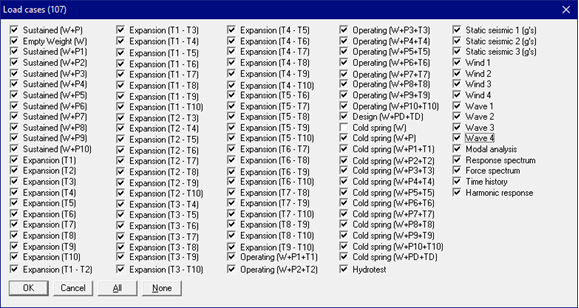
Load cases you can select for analysis
Automatic Spring Hanger design from a library of 35 hanger catalogs
Modal Analysis - Fast Eigenvalue solver
Seismic Response Spectrum Analysis
- Uniform response spectrum analysis
- Multi-level response spectrum analysis
- Spectrum input can be in the form of:
- Frequency (or period) versus Displacement
- Frequency (or period) versus Velocity
- Frequency (or period) versus Acceleration
- Linear or logarithmic interpolation
- Multiple units supported
- Spectra can be entered interactively or through a text file
- Missing mass (left-out force) correction for Uniform response spectrum can be included.
Combination Method can be:
- Square Root of Sum of Squares (SRSS)
- Absolute (ABS) Sum
- Closely Spaced Modes as per USNRC Reg. Guide 1.92
- Naval Research Laboratory (NRL) Sum
Level Summation for Multi-level can be:
- Square Root of Sum of Squares (SRSS)
- Absolute (ABS) Sum
Random Vibration Analysis
- Random Vibration analysis of piping, tubing & ducting in aircraft, aerospace and defense industries
- Power Spectral Density (PSD) data can be entered interactively or through user created text file or through user defined PSD library
- Response to Power Spectral Density (PSD) load by Normal Mode (Approximate) or by Normal Mode (Standard) method
- Power Spectral Density (PSD) input can be in the form of:
- Displacement versus Frequency (or period)
- Acceleration versus Frequency (or period)
- Linear or Logarithmic interpolation
- Multiple units supported
- Probability factors: 1 Sigma (68.27%), 2 Sigma (95.45%) and 3 Sigma (99.73%)
- Combination Method can be:
- Square Root of Sum of Squares (SRSS)
- Absolute (ABS) Sum
- Closely Spaced Modes (CSM) as per USNRC Reg. Guide 1.92
- Naval Research Laboratory (NRL) Sum
- Detailed Fatigue Calculations as per Steinberg’s Method
Time History Analysis
- Time functions can be input inside CAEPIPE or imported from a text file
Harmonic Analysis
Force Spectrum Analysis
- Force spectra functions can be input inside CAEPIPE or imported from a text file or can convert existing time functions into force functions.
- Pressure Relief Valve loading analysis.
FRP Piping Analysis (with user-specified stress allowables in different directions)
Buried piping analysis including automatic discretization of elements as per ASME B31.1
Refinement of Nodal Mesh based on user-input Mass Modeling Frequency
Refinement of Branch Elements to compute Flexibility Factors at Branch in accordance with ASME B31J
Internal and External Pressure Design of pipe and pipe fittings as per SS EN 13480-3 (2017)
Flange Qualification
- Flange & Bolt stresses as per ASME Section VIII Division 1
- Flange with High Strength Bolts as per NC.3658.3 of ASME Section III Class 2 (2017)
- Flange equivalent pressure as per
- NC.3658.1 of ASME Section III Class 2 (2017)
- Eq. 6.6.1-2 of EN 13480-3 (2020)
Calculation of allowable loads on nozzles to spherical and cylindrical shells as per EN 13445-3:2014/A8:2019
Calculation of local shell stresses as per WRC Bulletin 537 and evaluation of those stresses as per ASME Section VIII, Division 2 for Nozzles attached to Cylindrical and Spherical Vessels
Evaluation of Hollow Circular Attachment (Lug) and Solid Rectangular Attachment (Lug) welded to Pipe as per ASME Section III, Division 1 (NC & ND) and EN 13480.
Computation of Design Wind Forces as per ASCE/SEI 7-16
Computation of Static Seismic g's as per ASCE/SEI 7-16
Snow & Ice loads as per ASCE/SEI 7-22
Computation of Design Wind Forces as per EN 1991-1-4 (2010)
Dynamic generation of Elastic and Design Response Spectrum as per EN 1998-1:2004
Remaining Strength of Corroded Pipeline evaluation as per ASME B31G (2023)
Simplified Fatigue Evaluation for the applicable piping codes
Detailed Fatigue Evaluation with applicable guidelines from ASME Section VIII Division 2 (2021)