
Software Solutions
- CAEPIPE 3D+
- dataTRANSLATORS
- checkSTRESS
- HOTclash
- PEXit
- Pricing Request
- Download CAEPIPE 3D+
- Download Free Evaluation
- Download Free Review Module
- Customer Support
Engineering Services
- Design and Engineering
- INFOplant™ System
- Engineering Management
- List of Projects
- Project Gallery
- Project Videos
Learn More
Company Information
Incorrect Limit Stop Modeling
User Question: I see wind load results even when I have turned Wind load off. What am I doing wrong?
Reply: Upon examining the input data closely, we found this input data (see image below) for the limit stops. Can you identify what is wrong with the data in the boxed area?
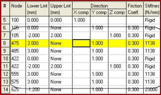
This model has limit stops at node 475, 485, 555 and 575 with Upper Limit as "None" and Lower Limit as "3.00 mm". This means that the pipes are being pushed to 3 mm in the +Y direction. But, in CAEPIPE, the UL (upper limit) has to be algebraically greater than the LL (lower limit).
This input error results in a movement of 3 mm, which generates forces and moments internally irrespective of whether Wind (or any other load) is being applied or not, It may be considered as a kind of a "preload." The solution, of course, will be to replace the Lower Limit of 3 mm with -3 mm (or 0 mm, if that is what the designer intended) such that it produces expected results.