Software Solutions
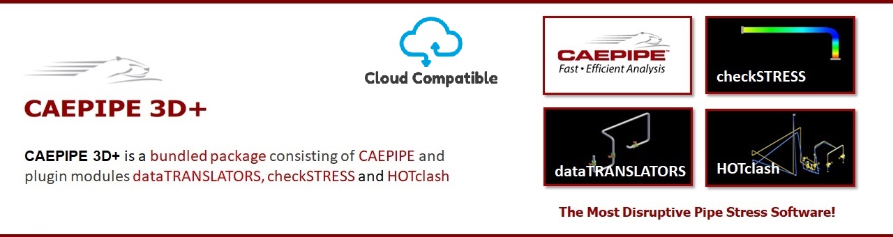
- CAEPIPE 3D+
- dataTRANSLATORS
- checkSTRESS
- HOTclash
- PEXit
- Pricing Request
- Download CAEPIPE 3D+
- Download Free Evaluation
- Download Free Review Module
- Customer Support
Engineering Services
- Design and Engineering
- INFOplant™ System
- Engineering Management
- List of Projects
- Project Gallery
- Project Videos
Learn More
Company Information
Empowering Piping Designers and Engineers with Speed, Precision, and Versatility
Unique Features of CAEPIPE 3D+
Download
Why CAEPIPE 3D+?
It is common practice worldwide that piping layout designers route pipes in 3D Plant Design systems with consideration given mainly to space constraints, process and flow constraints (such as pressure drop) and other requirements arising from constructability, operability and reparability. Most often, while routing piping systems, pipe stress requirements are not sufficiently considered.
In order to meet pipe stress requirements, pipe stress engineers have all along felt the following needs.
Need 1: Instead of creating pipe stress models by manually entering layout, pipe sizes and materials, supports, loads etc. in pipe stress software such as CAEPIPE, such stress models should be generated directly from 3D Plant Design systems.
Need 2: The layouts of the stress models so generated from 3D Plant Design systems should have already gone through first-level stress compliance checks performed by 3D piping designers, so that the piping layouts received by pipe stress engineers are already flexible enough to absorb expansion/contraction of pipes due to thermal loads.
Need 3: In addition to the traditional “clash checks” carried out on 3D plant model, piping designers should be able to check for “interference” when piping is deformed under “hot operating condition”.
Need 4: Immediate visualization of the 3D plant model while performing detailed analyses would immensely help pipe stress engineers to identify (a) all possible locations for pipe supports and (b) vacant space available in case re-routing of pipes is required.
Need 5: Piping designers should be able to import any layout changes made by stress engineers to 3D plant model as “reference geometry” for re-routing, and update pipe supports in 3D plant model by referring to finalized stress models.
SST Systems’ disruptive product CAEPIPE 3D+ fulfils all 5 Needs of pipe stress engineers as outlined in the respective features below.
Feature 1:
CAEPIPE 3D+ meets Need 1 by generating pipe stress models directly from 3D Plant Design systems such as E3D/PDMS, SmartPlant, AutoCAD Plant 3D, AutoPlant, CADMATIC, CATIA, etc.
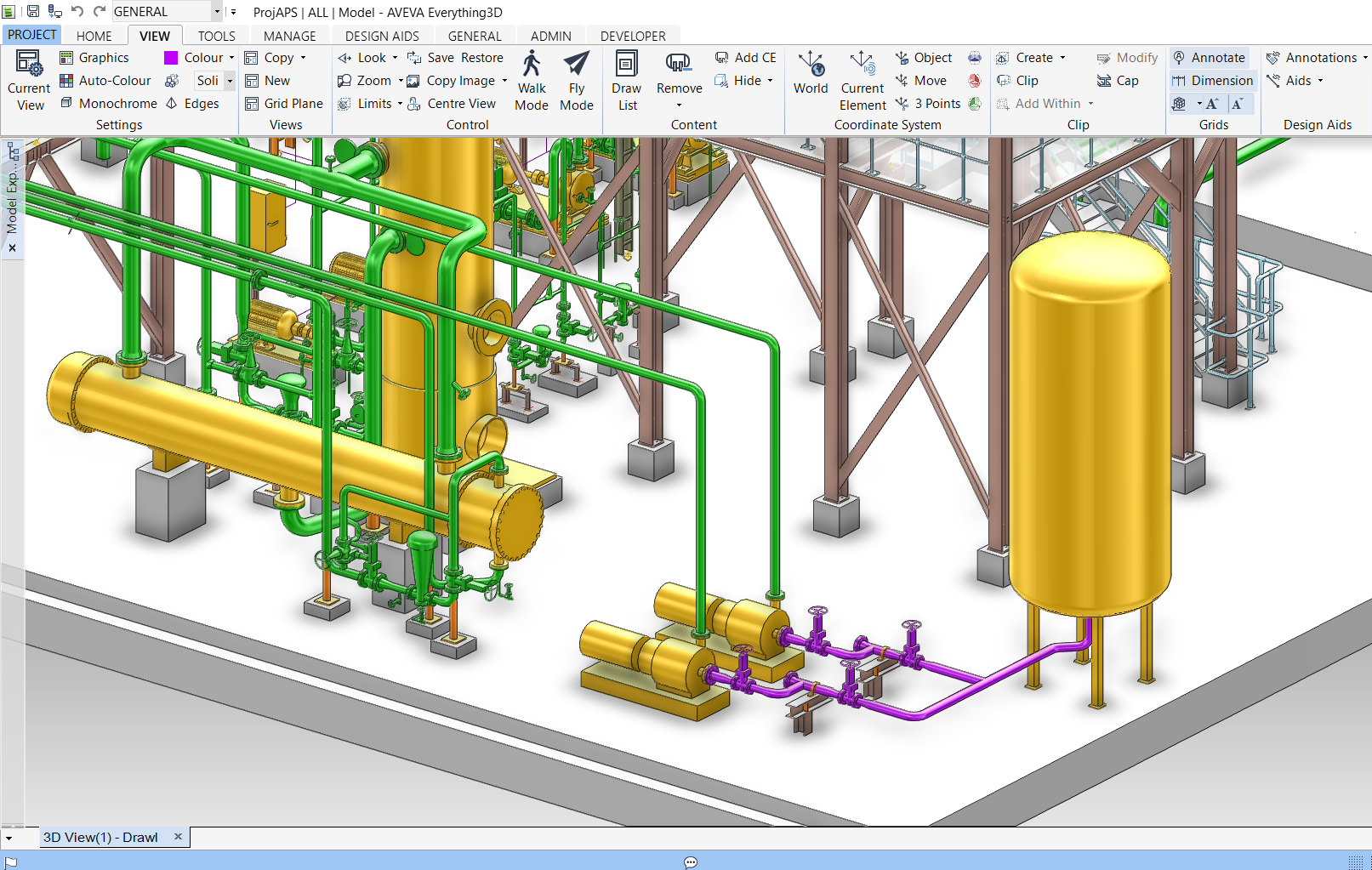
Stress Model generated by Designer from 3D Plant Design System
Feature 2:
Need 2 is met by first having 3D piping designers use CAEPIPE 3D+ as first-level piping flexibility check software. In other words, while pipe routing, 3D piping designers use CAEPIPE 3D+ to perform a few basic stress compliance checks, specifically to make sure the layouts are flexible enough to absorb thermal expansion/contraction of pipes.
First-level Stress Check on Original Layout by Designer
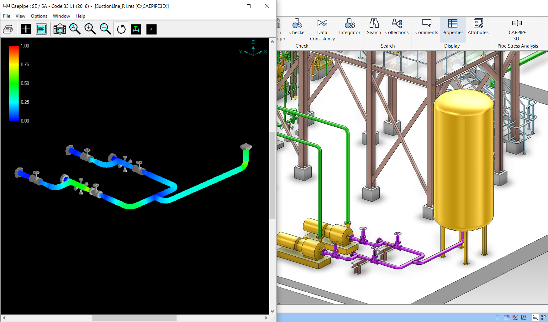
First-level Stress Check on Revised Layout by Designer
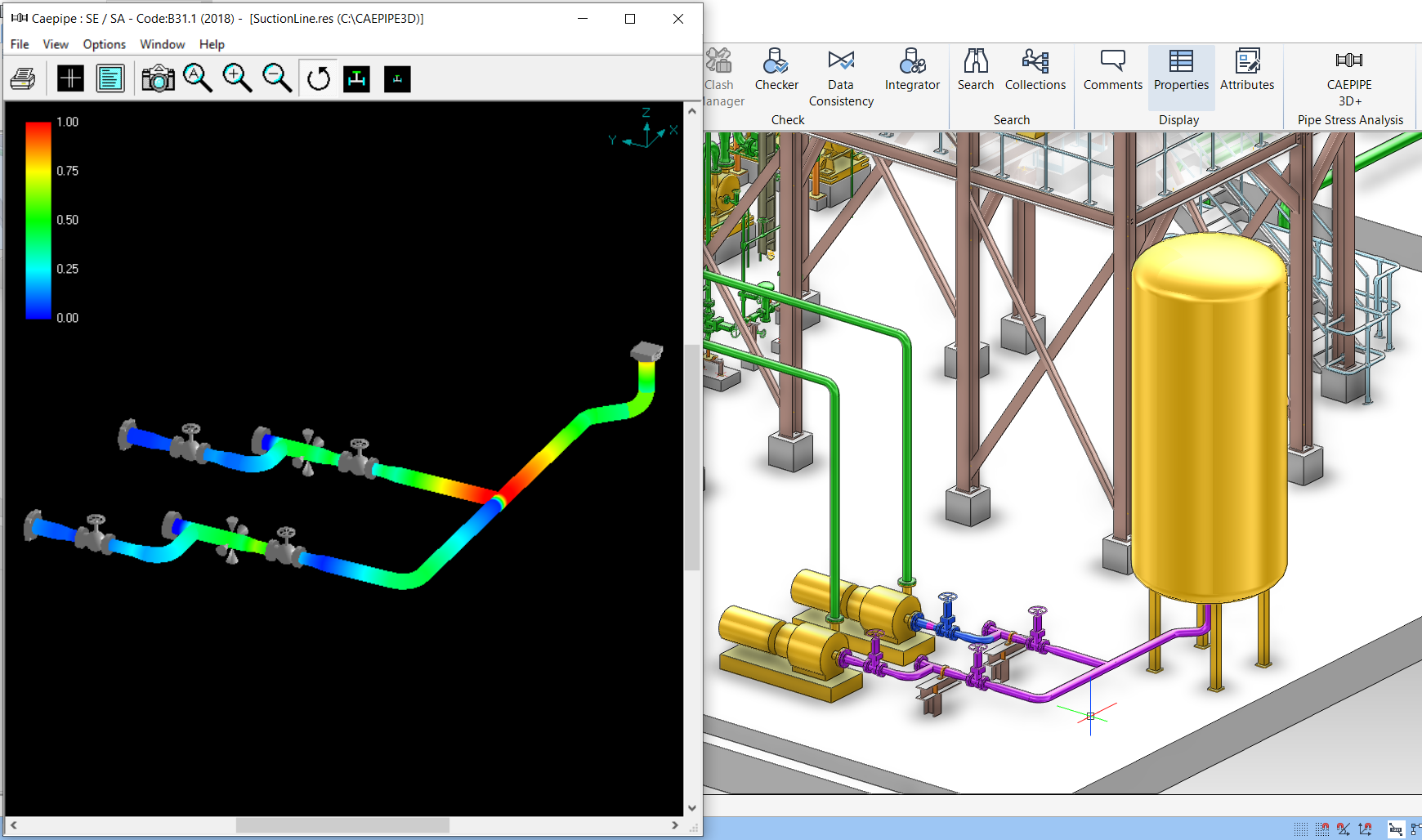
Feature 3:
Once 3D piping designers finalize the layouts after performing first-level piping flexibility checks, they can meet Need 3 by using CAEPIPE 3D+ to check for interference between the “deformed” layouts of piping under “hot operating condition” and adjacent objects. This feature is available only on CAEPIPE 3D+ for E3D/PDMS and CADMATIC. To avoid any interference under hot condition, designers can make minor layout changes.
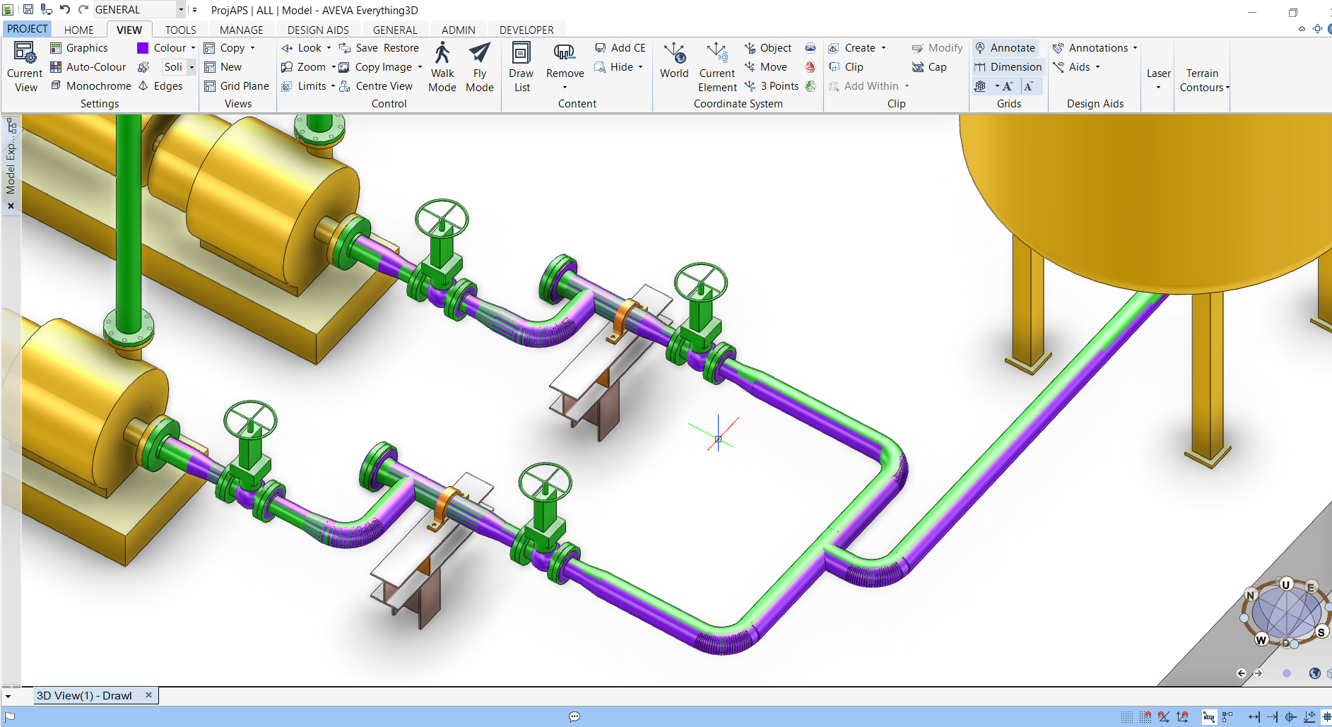
Clash Check under HOT Condition by Designer
Feature 4:
The “thermal stress-compliant” and “hot-clash-free” CAEPIPE 3D+ models resulting from Features 2 and 3 are transferred to pipe stress engineers (a) to carry out detailed analyses for loads such as deadweight, thermal, wind, seismic and dynamic loads, (b) to arrive at proper support scheme to meet all aspects of pipe stress requirements, and (c) to generate detailed stress reports.
CAEPIPE 3D+ meets Need 4 of pipe stress engineers by providing immediate visualization of the 3D plant model while performing analyses. Such instant visualization helps (a) to identify all possible locations for pipe supports, and (b) to identify vacant space available in case re-routing of pipes is required.
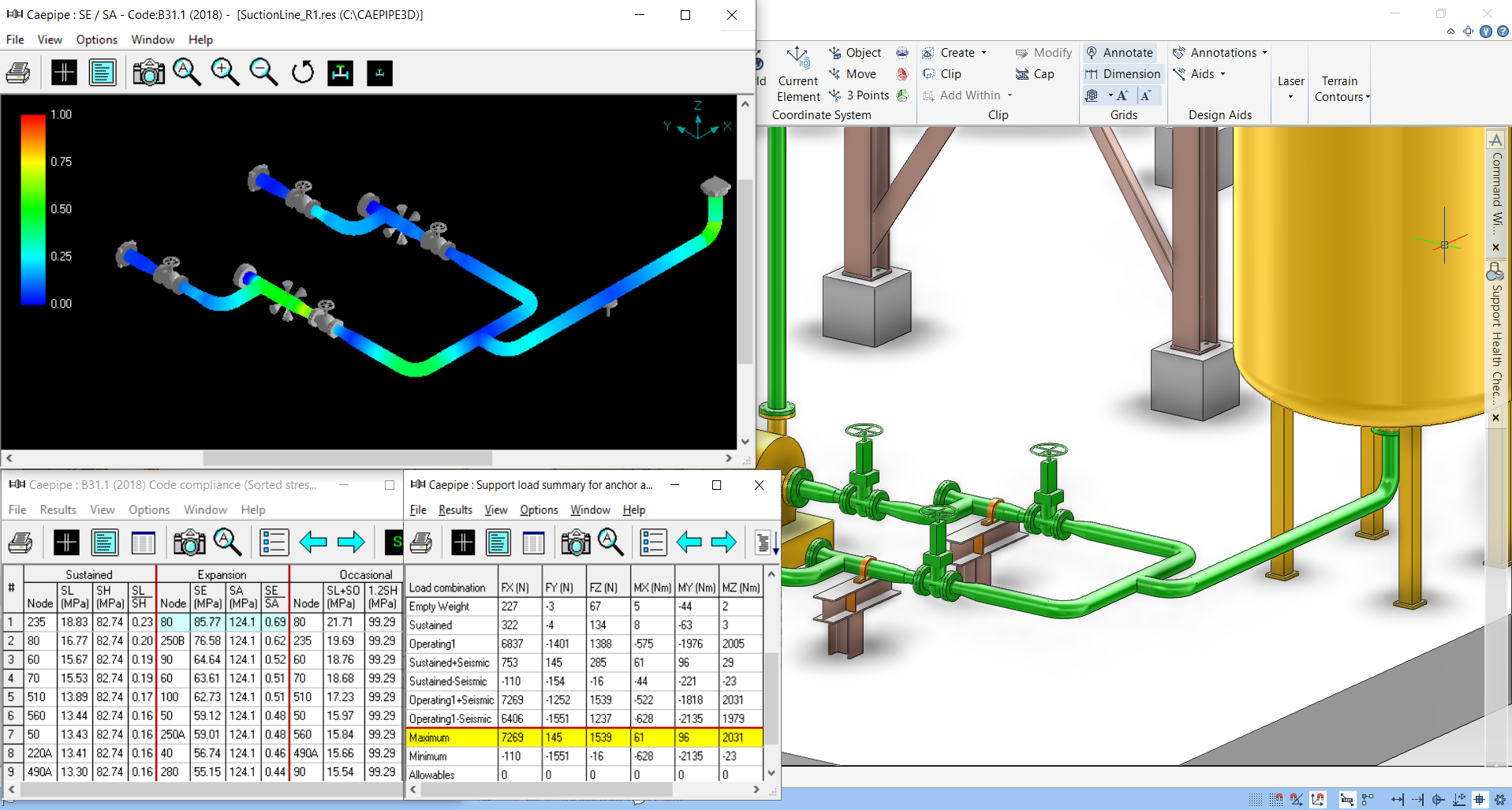
Detailed Analysis by Stress Engineer with 3D Plant Model in view
Feature 5:
Once stress models are finalized by pipe stress engineers, CAEPIPE 3D+ meets Need 5 by allowing piping designers to import all layout changes made by stress engineers into 3D plant model as “reference geometry”, over which designers would re-route pipes. Designers would then update pipe supports in 3D plant model by referring to finalized stress models.
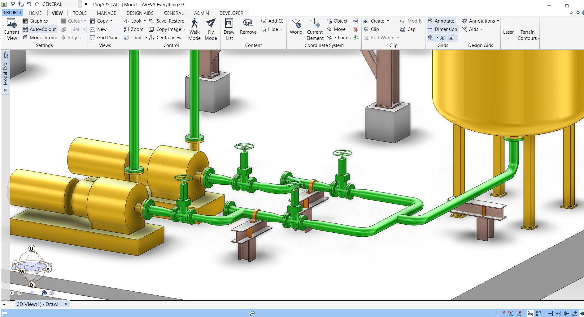
Finalized Layout & Supports transferred to 3D Plant by Designer
Overview of CAEPIPE 3D+
Pipe stress software CAEPIPE 3D+ has two (2) parts built-in as listed below.
Part 1 generates pipe stress models in CAEPIPE 3D+ format from:
- Plant database of 3D Plant Design software E3D/PDMS and CADMATIC, and
- PCF files generated from plant database of 3D Plant Design software such as SmartPlant, AutoCAD Plant 3D, AutoPlant, CATIA, CADWORX, etc.
- Piping geometry, pipe sections and material properties,
- Temperature, pressure and weight of pipe fittings,
- Thermal anchor movements at equipment nozzles,
- Allowable loads at equipment nozzles, and
- Pipe support details to create the corresponding hangers, guides, etc. in CAEPIPE 3D+.
by reading the following from the plant database / PCF files of the above 3D Plant Design software:
Part 2 of CAEPIPE 3D+ is the same as the full-fledged internationally accepted pipe stress software CAEPIPE, which reads the stress models generated through Part 1. For modeling and analysis features of CAEPIPE, review CAEPIPE User’s Manual, Technical Reference Manual and Code Compliance Manual available at the link www.sstusa.com/caepipe-docs.php.
Flexible Usage of CAEPIPE 3D+
Each licensed seat of CAEPIPE 3D+ currently allows the use of the following 5 modules, with the only restriction being only one module can be used at any point in time. As listed below, CAEPIPE 3D+ can be used as a stand-alone CAEPIPE in case 3D plant database or PCF files are not available to work with.
- CAEPIPE 3D+ for E3D/PDMS*
- CAEPIPE 3D+ for CADMATIC*
- CAEPIPE 3D+ for PDS
- CAEPIPE 3D+ for PCF files generated by 3D Plant Design Systems such as SmartPlant, AutoCAD Plant 3D, AutoPlant, CATIA, CADWORX etc.
- CAEPIPE (stand-alone)
In short, all five modules are available for use by a licensed CAEPIPE 3D+ seat, but only one module at any point in time.
*CAEPIPE 3D+ runs as an on-line, add-on module to E3D/PDMS/CADMATIC, whereby a 3D piping designer transfers piping layouts and all available data from E3D/PDMS/CADMATIC to CAEPIPE 3D+ directly and performs first-level stress compliance checks without exiting E3D/PDMS/CADMATIC. Similarly, a pipe stress engineer performs detailed analyses of stress models received from the 3D piping designer without exiting E3D/PDMS/CADMATIC.
Benefits of CAEPIPE 3D+
- The same full-fledged pipe stress software CAEPIPE 3D+ is used with many 3D Plant Design systems or as a stand-alone stress software, based on the requirements of projects.
- CAEPIPE 3D+ input files can be generated directly from 3D Plant Design systems, thereby saving time and avoiding errors in re-creating stress models manually.
- CAEPIPE 3D+ can be used first by 3D piping designers as a first-level piping flexibility check software. This step substantially reduces the number of design iterations between the piping layout and stress departments, resulting in huge time saving during design.
- Using CAEPIPE 3D+ module for E3D/PDMS/CADMATIC, 3D piping designers can check for interference between “piping deformed under hot operating condition” and adjacent objects.
- When CAEPIPE 3D+ is used on E3D/PDMS/CADMATIC, 3D plant model can be instantly viewed by 3D designers during their first-level stress checks and by pipe stress engineers during detailed analyses.
- Stress analysts can identify all possible locations for pipe supports on 3D plant model, as it contains all supporting objects such as steel and concrete structures adjacent to the concerned piping systems. These possible pipe support locations, once marked in the 3D plant model, are automatically transferred as “nodes” in the CAEPIPE 3D+ input files.
- Piping designers can import layout changes made by stress engineers into 3D plant model and update pipe supports by viewing final stress models, resulting in significant time saving during design.
In summary, CAEPIPE 3D+ helps 3D piping designers and stress engineers to arrive at substantially better piping layouts that also meet all stress requirements, thereby saving costs associated with design, materials, construction, operation and maintenance.
Analytical Capabilities of CAEPIPE (built into CAEPIPE 3D+)
CAEPIPE provides an advanced, fully integrated analysis platform that solves both linear and nonlinear problems across a wide range of loading conditions.
Static Analysis
CAEPIPE offers a wide range of static analysis capabilities to address real-world loading conditions. It accounts for deadweight of piping and components, multiple thermal load and pressure scenarios (supporting up to 10 each), and additional loads such as hydrotest, snow or ice accumulation, internal linings, and cladding. The software allows engineers to incorporate support displacements caused by foundation settlement or nozzle movements. It can also simulate static equivalent loads from seismic and wind events, wave loading for offshore applications, and perform specialized analyses for buried piping systems.
Dynamic Analysis
Dynamic behaviour of piping systems can be thoroughly evaluated in CAEPIPE. It includes modal analysis to identify natural frequencies up to 9999 Hz. Engineers can perform response spectrum analysis - either uniform or multi-level - as well as time history simulations using the Wilson-θ integration method. The software supports harmonic excitation studies and fluid transient effects, including pressure relief valve (PRV) events, fluid hammer, and slug flow. For impulsive loading scenarios, CAEPIPE provides force spectrum analysis to capture system response accurately.
Equipment and Pressure Design Codes
CAEPIPE supports a wide range of equipment design codes to ensure reliable nozzle load compliance. For pumps, it follows API 610, API 676 and ANSI/HI 9.6.2 standards. Compressors are covered under API 617, feedwater heaters are covered under HEI 2622 and air-cooled heat exchangers are covered under API 661. Steam turbines are evaluated using NEMA SM-23. For pressure vessels and nozzle-to-shell connections, CAEPIPE supports ASME Section VIII Division 2 and WRC 537. It also includes European standards like EN 13445 and EN 13480-3 for unfired pressure vessels and for piping systems respectively. These codes help assess the structural integrity of equipment under piping-induced loads.
Corrosion and Fatigue:
CAEPIPE provides tools for assessing corrosion and fatigue in piping systems. It evaluates remaining strength of corroded pipes using ASME B31G. For fatigue, CAEPIPE performs both simplified fatigue evaluation as required by applicable piping codes, and detailed fatigue evaluation following the guidelines of ASME Section VIII Division 2.
Global Piping Code Compliance
- ASME: B31.1, B31.3, B31.4, B31.5, B31.8, B31.9, B31.12, Section III NC/ND
- EN / ISO: EN 13480-3, EN 13941-1, EN 1998-1, ISO 14692-3
- National Codes: RCC-M, CODETI, IGEM (UK), BS 806, DNV-ST-F101, Z662 (Canada), Stoomwezen (Netherlands)
Modelling Environment: Designed for Efficiency and Ease of Use
CAEPIPE 3D+, if used as CAEPIPE on a stand - alone basis, streamlines modelling with its unique Layout Window, where piping elements are entered row-wise like scripting. This allows users to model without drag-and-drop, and instead use concise text commands and shortcuts:
Shortcut-based Modelling
CAEPIPE allows users to create and edit piping models using simple keyboard shortcuts and intuitive commands - instead of relying entirely on graphical drag-and-drop or mouse input. This significantly speeds up model creation, especially for large and repetitive piping layouts.
Key Benefits:
- Faster Input: You can define long runs of pipe, elbows, supports, valves, reducers, etc., using single-letter commands (like B for bend, R for reducer, A for anchor).
- Minimal Mouse Use: Most actions can be completed directly from the keyboard, which is particularly helpful for power users and experienced engineers.
- Copy/Paste Efficiently: You can duplicate parts of your model or reuse sub-models by simply copying rows and pasting them elsewhere.
- Quick Editing: You can edit coordinates, properties, and loads directly in the spreadsheet-like layout - as fast as editing an Excel sheet.
Distinct Features of CAEPIPE 3D+
Jacketed Piping
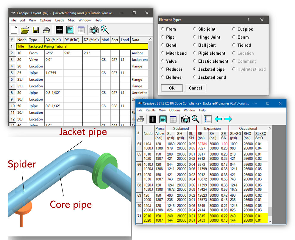
CAEPIPE 3D+ simplifies the modelling of jacketed piping systems using dedicated element types -Jacketed pipe and Jacketed bend - that allow simultaneous routing of both core and jacket components. Users can assign material, section, and load separately for core pipe and jacket pipe through an intuitive interface. The pipe route needs to be modelled only once, making any future modifications quick and consistent. CAEPIPE automatically handles the dual-pipe relationship, and results are generated for both pipes. Jacket pipe results are clearly identified using node labels ending in “J,” making interpretation straightforward. This feature streamlines jacketed piping analysis with minimal user effort.
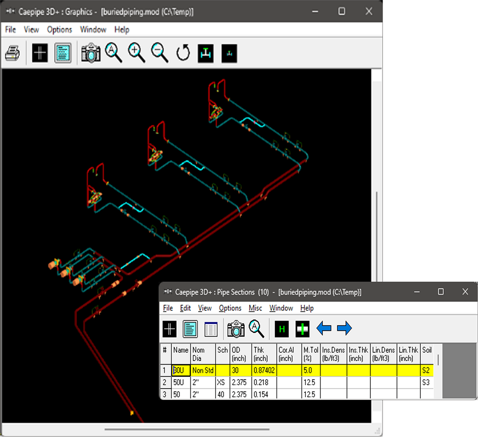
Buried Piping
CAEPIPE offers robust capabilities for analysing buried piping systems through integrated soil-structure interaction modelling. Engineers can assign different soil types, burial depths, and pipe slopes along the pipeline, allowing accurate simulation of underground p/iping behaviour. The software supports PUR (Polyurethane) expansion cushion modelling, which is commonly used in pre-insulated piping systems. Additionally, CAEPIPE makes it easy to switch between above-ground and below-ground modelling, streamlining the design and analysis of pipelines that transition between exposed and buried conditions.
Fatigue Analysis
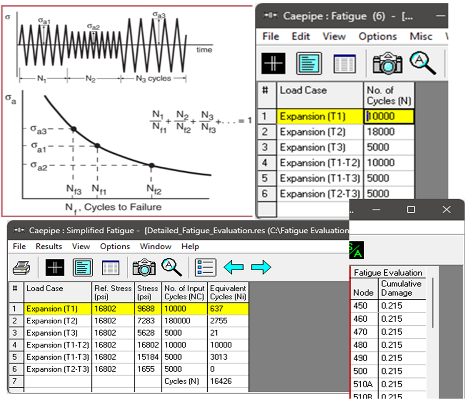
CAEPIPE 3D+ provides both simplified and detailed fatigue evaluations based on guidelines from ASME Section VIII Division 2. The detailed method applies Miner’s Rule to assess cumulative damage using S-N curves, enabling node-by-node checks for potential fatigue failure. The simplified approach computes equivalent stress range cycles and applies stress range reduction factors as per the selected piping code. Users can input actual cycle counts for each expansion load case, and CAEPIPE calculates fatigue life accordingly. This helps engineers ensure safe stress layouts and optimize piping design against fatigue.
Static and Dynamic Analyses in one place
CAEPIPE 3D+ seamlessly integrates both static and dynamic analyses within a single module, allowing engineers to evaluate piping systems under various loading conditions without switching tools or duplicating models. Users can define all relevant load cases including thermal, pressure, seismic, wind, and dynamic events - and perform comprehensive analysis in one workflow. This unified approach simplifies modelling, saves time, and ensures consistency across all results, whether evaluating stresses or dynamic responses.
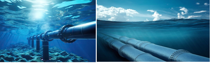
Wave Loading
CAEPIPE supports Morison equation-based wave force calculations for offshore and coastal piping systems, enabling accurate analysis of environmental loading. It incorporates both vertical and horizontal particle velocities from wave motion, ensuring realistic dynamic force evaluation. Users can either specify a preferred wave theory—such as Airy, Stokes, Cnoidal—or let CAEPIPE automatically select the most appropriate theory based on pipe and wave parameters. Wave loading can be applied to the entire piping system or to specific segments, providing flexibility in modelling complex marine conditions.
Random Vibration (Exclusive)
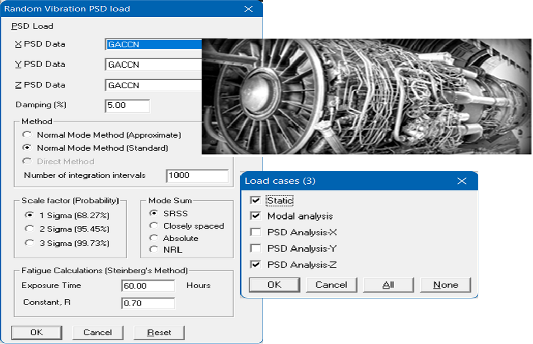
CAEPIPE enables response to random vibration environments by accepting Power Spectral Density (PSD) inputs, which characterize the intensity of vibration across a range of frequencies. For modal summation, it supports industry-standard methods such as Square Root of the Sum of Squares (SRSS), Absolute Sum (ABS), and Complete Quadratic Combination (CQC) in accordance with USNRC Reg. Guide 1.92. Fatigue life is evaluated using Steinberg’s method, a proven approach for electronic and mechanical systems under random vibration. This capability makes CAEPIPE particularly well-suited for aerospace, defence, and offshore industry applications where vibration-induced fatigue is a key concern.
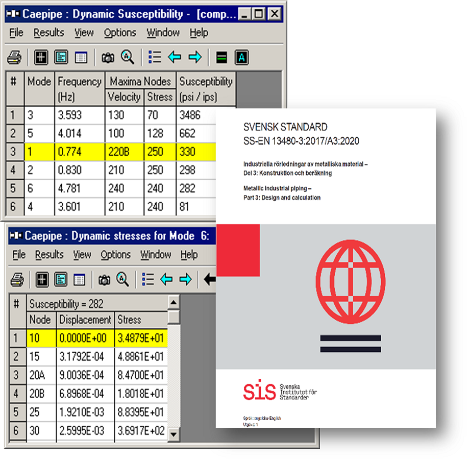
Dynamic Susceptibility (Exclusive)
Dynamic Susceptibility in CAEPIPE 3D+ is a unique capability that helps assess the risk of vibration-induced stresses in piping systems. It calculates the Dynamic Susceptibility Factor (DS) for each natural frequency mode defined as the ratio of dynamic bending stress to vibration velocity - to identify potential dynamic hotspots. CAEPIPE provides visual identification of critical locations through color-coded mode shapes. Importantly, this method is referenced in Clause A.2.7 of EN 13480-3:2017/A3:2020, which recognizes its value during the design, commissioning, and operation phases. Engineers can use it to detect high-risk modes, guide inspections, inform placement of measurement sensors, and define velocity screening thresholds—making it a valuable tool for vibration management throughout a piping system’s life cycle.
What Sets CAEPIPE 3D+ Apart?
- Data Translators from almost all 3D plant design systems (dataTRANSLATORS)
- Hot-operating Clash Detection (HOTclash)
- Real-time Stress Checking in CAD Systems (checkSTRESS)
- Simultaneous core and jacketed pipe stress results
- Buried + above-ground piping in one model
- Dynamic Susceptibility: No other commercial software offers it
- Auto-grouping of Load Cases: Automatically combines relevant load cases based on analysis code.
- Free graphical viewer for stakeholders (Review Module)
- Free Evaluation software: Up to 20 rows (Stand-alone Eval Module)
Additional Unique Features of CAEPIPE 3D+
- Segmented and Directional Wind/Wave/Seismic Load Handling: Easily apply wind/wave /seismic loads selectively to model regions or directions.
- Custom Fatigue Curve Import: Supports user-defined S-N curves (e.g., from manufacturer test data) for detailed fatigue evaluation.
- Nozzle Flexibility Modelling: Includes vendor-defined or code-based flexibility for nozzle connections without needing external FEA.
- Fatigue Check at Each Node: Node-by-node fatigue damage check using cumulative damage theory (Miner’s Rule).
- Batch Analysis Mode: Automatically runs multiple what-if scenarios and outputs summary results for quick comparisons.
- Integrated Report Generator: One-click generation of Formatted code-compliant PDF reports with plots, diagrams, and result tables.
- Cloud Licensing Option: Available for distributed teams or consultants needing flexible access.
CAEPIPE empowers both designers and stress engineers to collaborate, validate, and optimize piping routes in real-time.
Speed and Accuracy: Where CAEPIPE 3D+ Excels
The analysis engine is built around a custom Skyline Matrix Solver, which is:
- Optimized for sparse matrix structures
- Capable of handling nonlinearities with minimal iterations
- Not reliant on external algebra libraries
- Performs static and dynamic analysis in a single run
CAEPIPE can process complex, large-scale models with remarkable speed and minimal memory footprint.
Practical Engineering Benefits
- Accelerate Design Cycles: Designers can do early checks
- Reduce Errors: Integrated tools like HOTclash prevent rework
- Improve Collaboration: Import/export with major platforms
- Streamline Reporting: Formatted, indexed, exportable reports
- Support for Codes & Components: Compliance is built-in
- Easy to Learn: New users can learn CAEPIPE 3D+ quickly.
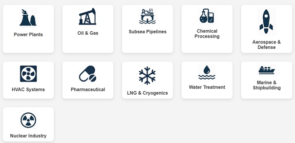
Use cases include:
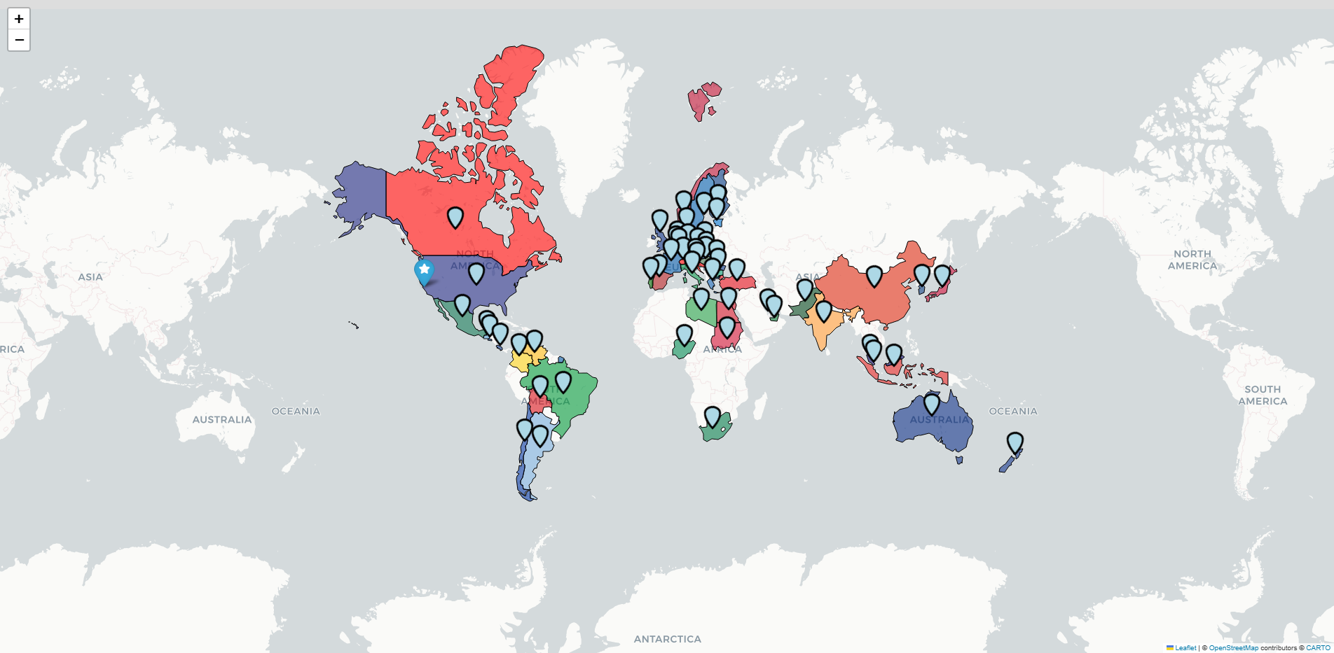
Our clients are spread in the following countries: