
Software Solutions
- CAEPIPE 3D+
- dataTRANSLATORS
- checkSTRESS
- HOTclash
- PEXit
- Pricing Request
- Download CAEPIPE 3D+
- Download Free Evaluation
- Download Free Review Module
- Customer Support
Engineering Services
- Design and Engineering
- INFOplant™ System
- Engineering Management
- List of Projects
- Project Gallery
- Project Videos
Learn More
Company Information

What's New in Version 15.00? Download
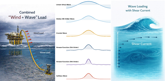
Wind + Wave
Key advancements in this release include expanded wave load analysis capabilities with the addition of advanced wave theories and improved convergence algorithms, allowing for more precise modeling of nonlinear wave behavior. The introduction of combined wind and wave load cases further enhances the ability to simulate realistic operating conditions for offshore and partially submerged piping systems.
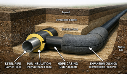
Buried Piping Analysis
In buried piping analysis, cushion density can now be directly incorporated within the soil model, allowing its weight to be automatically included in the analysis and improving overall modeling consistency.
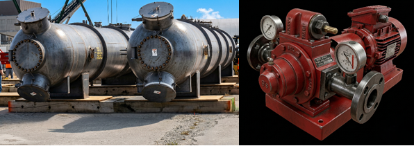
Equipment Evaluation
Broadens Equipment evaluation capabilities with the addition of API 676 for Positive Displacement Pumps and HEI 2622 for Feedwater Heaters, allowing more comprehensive nozzle load assessments.
Updated Piping Codes
- ASME B31.8 (2025)
- CSA Z662 (2023)
- EN 13480 (2024)
Enhancements
- Material library corresponding to ASME B31.8 (2025) is added. Refer to Piping Code Compliance section of CAEPIPE Code Compliance Manual for details.
- Wave Load Analysis now includes three (3) additional Wave Theories namely Fenton's Stream, Dean Dalrymple Stream and Solitary (Munk/McCowan) with the option for the user to input the wave order from 1 to 31 for Fenton's Stream and Dean Dalrymple Stream Theories. So, starting version 15.00, for Wave Load Analysis, the user has the option to select any of six (6) Wave Theories, namely, Airy's Linear, Stokes 5th Order, Cnoidal 5th Order, Fenton's Stream, Dean Dalrymple Stream and Solitary (Munk/McCowan).
- Improved convergence routine for Cnoidal Wave Theory in Wave Load Analysis.
- New feature is added to combine 4 Wind Loads with 4 Wave Loads simultaneously in Occasional Stress computation, useful to analyse offshore piping, partially above water level and exposed only to wind, and the balance under water experiencing only wave loading. With the inclusion of these load cases, CAEPIPE now has the ability to define 115+ load cases and Support Load Summary for 280+ load combinations.
- Hydrotest Stress evaluation is now added for EN 13480-3 (2024). This Hydrotest Stress evaluation can be seen through CAEPIPE Results Window > Results > Results... > Sorted Stresses and CAEPIPE Results Window > Results > Results... > Code Compliance.
- New feature is added to use "Restrained" equations for above ground piping located between Intermediate Anchors for piping codes ASME B31.4, ASME B31.8, ASME B31.12 Pipeline Systems, EN 13480-3 and CSA Z662. This can be performed by defining PROXY soil and assigning the same to the "Restrained" piping sections. For further details, refer to the Section titled "Soil" in CAEPIPE Technical Reference Manual.
- For cohesive soil, if the soil strength specified is greater than 250 kN/m2 (0.25 MPa or 250 psi) and the resulting adhesion factor is calculated to be less than 0.211, the system internally applies a minimum value of 0.211 for adhesion factor.
- A new feature has been added to the Soil dialog allowing users to input Cushion Density. When provided, the cushion’s weight is now computed and included in the analysis.
- New feature is added to assess piping loads applied to nozzles on Positive Displacement Pumps in accordance with API 676 (2022). For further details, refer to the Section titled "Pump" in CAEPIPE Technical Reference Manual and the Section titled "API 676" in CAEPIPE Code Compliance Manual.
- New module added to calculate allowable nozzle loads for Nozzles connecting to Heat Exchanger as per HEI 2622 - Feedwater Heaters (2015). This module can be accessed through CAEPIPE Main Window > New > Nozzle Qualification. For further details, refer to the Section titled "Nozzle Evaluation" in CAEPIPE Technical Reference Manual and the Section titled "HEI 2622" in CAEPIPE Code Compliance Manual.
- "Design Pressure" and "Design Temperature" have been renamed as "Peak Pressure" and "Peak Temperature" respectively in Load dialog. In addition, a new feature is added to compute "Peak pressure factor" internally using "Peak Pressure" and "Maximum Operating Pressure" when the option "Compute peak pressure factor using (Ppeak/Pmax)" is turned ON through Layout Window > Options > Analysis > Pressure". Refer to the Section titled "Load" in CAEPIPE Technical Reference Manual and the Sub-section titled "Pressure" in CAEPIPE User's Manual for details.
- New feature is added to reverse the portion of the stress layout. This can be performed by using the command Layout Window > Edit > Reverse and Paste. For further details, refer to the Section titled "Reverse and Paste" in CAEPIPE User's Manual.
- New feature is added to the Generate command. This command now supports duplicating layouts created with Absolute Coordinates. As part of this enhancement, the release also automatically updates the node number in the ‘Connected To’ fields within the Support Data types to maintain proper connectivity, if input.
- A new feature has been added to prevent users from finding spring hangers with a specified type and replacing them with spring hangers without a type in the Find and Replace command. In other words, the Type field cannot be left blank in the ‘Find and Replace’ command.
- A new feature has been added to prevent users from inputting Operating Temperatures, Peak Temperature and Reference Temperature below -460 deg. F (= -273.13 deg. C or 0 Kelvin).
- A new feature has been added to display a warning message when the selected analysis code differs from the piping code for the material library selected.
- A new feature allows users to select the Flange Equivalent Pressure method as ASME Class 2 (2023) or EN 13480-3 (2024), independent of the selected analysis code. This option can be accessed via Layout Window > Option > Analysis > Misc.
- New feature is added to print Sorted Stresses results for "Operating Stress for NDE" and "Operating Stress for Impact Test" to CSV and TXT file when the option is Turned ON.
- New feature is added to print Minimum & Maximum Displacements results for the selected load cases when the Displacements results are turned ON through Print Dialog.
- New feature is added to close the list window and change focus to Layout Window when the commands "Refine Nodal Mesh", "Refine Branches" and "Reverse & Paste" are used.
- The maximum file path length has been increased from 80 to 256 characters, allowing batch run paths to be up to 256 characters long.
- A new feature has been added to create a temporary file in the Local User directory, enabling support for long file names in the PCF file and avoiding write access issues.
- New feature is added in CAEPIPE 3D+ for PCF to transfer LAPJOINT-STUBEND as a Flange or Pipe by modifying the config_pcf.ini file. For details, refer to the Section titled "CAEPIPE 3D+ for PCF" in CAEPIPE 3D+ User's Manual.
- New features have been added to "CAEPIPE 3D+ for PCF" to enable smoother data transfer:
- When Continuous Rendering mode is enabled via Main Frame > File > Preferences, users can temporarily switch between Rendered and Line views using Graphics Window > View > Render or Do Not Render.
- Rendering of jacket piping and jacket connections (Spiders and Jacket End Caps) has been improved.
- New functionalities are added to the Mouse Operations for PAN and ROTATE
- MBF format is updated to be compatible with CAEPIPE Version 15.00. See Appendix A of CAEPIPE User's Manual for details.
- CAEPIPE User's Manual, Technical Reference Manual and Code Compliance Manual have been enhanced and updated to be in line with software version 15.00. These Manuals can be downloaded from the link www.sstusa.com/caepipe-docs.php.
Bug Fixes
- For API 661 Qualification, the allowable column was shown as "NA" when the Nozzle Diameter is 4" (100 mm).
- Printing the Equipment Qualification Report for API 610 to CSV and TXT file was issuing Access Violation at Random.
- Sorted Stresses result is not displayed for EN 13480 when the entire layout is buried below the soil.
- When a Relief Value Loading dialog was used more than once with a different Force Spectrum Name input, then it was using the Time Function data created for the first time from the back end to generate the new Force Spectrum data.
- Wave Load Case is turned OFF when Mean Sea Level is input as zero.
- Incorrect criterion value in Automatic Wave Theory selection caused Stokes Theory to be excluded for part of its valid regime.
- Selecting "Dynamic Susceptibility" results was issuing "Access Violation" when the Pipe Material Density is input as 0.0.
- Tensile Strength values were missing in the Material Library file B313-2024.mat.
- When selecting a material from a library file with a version earlier than 10.60 that uses an analysis code other than B31.1, B31.3, B31.9, B31.12 IP, Z183, Z184 and Z662, and applying it to a model whose analysis code is one of the codes listed above, the Tensile Strength value was incorrectly assigned to the Yield Stress field. For example, when selecting a material from the library file EN 13480-2012.mat for a layout using the analysis code ASME B31.1 (2024) , the system incorrectly mapped the Tensile Strength value to the Yield Stress value.
Now is the time to evaluate CAEPIPE!
Download
Release Announcement for Version 14.10
Release Announcement for Version 14.00
Release Announcement for Version 13.10
Release Announcement for Version 13.00
Release Announcement for Version 12.20
Release Announcement for Version 12.10
Release Announcement for Version 12.00